
Robotics IR Navigation Sensor

The Robotics IR Navigation Sensor Circuit utilizes an inverter IC, specifically the 74HC04, to process signals from the infrared (IR) sensors. This circuit is typically employed in robotic applications for navigation and obstacle detection. The 74HC04 contains six independent inverters, which can be used to amplify and condition the signals received from the IR sensors.
The IR sensors in this configuration emit infrared light and detect the reflection from nearby objects. When an object is detected, the reflected IR light is received by the sensor, which generates a corresponding electrical signal. The output of the IR sensor is then fed into one of the inverters on the 74HC04 chip. The inverter converts the signal, effectively changing its logic state, which can be used to trigger further actions in the robotic system, such as steering or stopping.
In addition to the 74HC04, the circuit may include passive components such as resistors and capacitors to filter noise and stabilize the operation of the sensors. The design must account for the operational conditions, ensuring that the IR sensors function effectively under various lighting conditions, including direct sunlight. This requires careful selection of the sensor type and possibly the implementation of additional circuitry to enhance performance in bright environments.
Overall, this circuit design is fundamental for creating autonomous robotic systems capable of navigating their surroundings efficiently by detecting and responding to obstacles in real time.The following circuit shows about Robotics IR Navigation Sensor Circuit Diagram. Features: one chip 74HC04, IR sensor will work in direct sun .. 🔗 External reference
Related Circuits
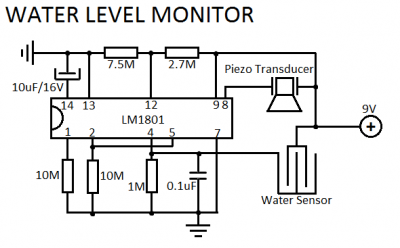
LM1801 Water Level Sensor Circuit Diagram. Features: reference voltage is overshot, and the IC drives the ceramic transducer to beep, low power consumption. The LM1801 water level sensor circuit utilizes the LM1801 integrated circuit, which is designed to monitor water...
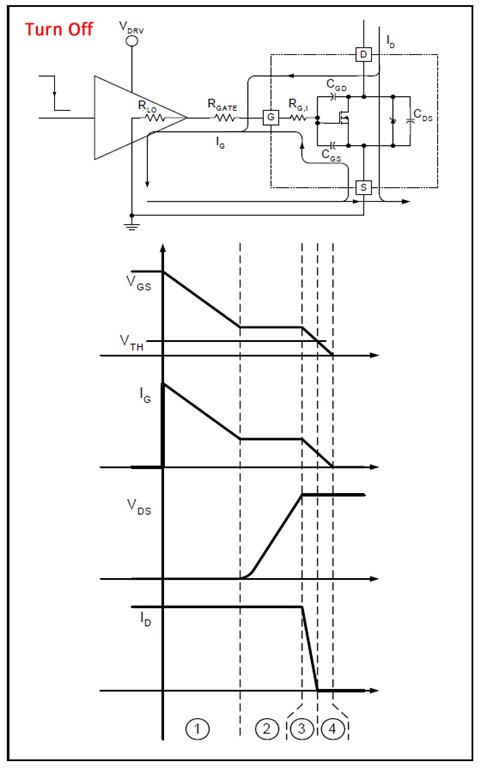
H-bridge applications for robots, robotics, and motor control. This post focuses on the low-side switch element. H-bridges are widely utilized in robotics and motor control applications to enable bidirectional control of DC motors. An H-bridge consists of four switches arranged...
This circuit utilizes a JFET to receive signals from an LED and buffer them. The output voltage is managed using an IC 1458 or LM1458, which provides approximately 7 volts in darkness and experiences a drop of about 2...
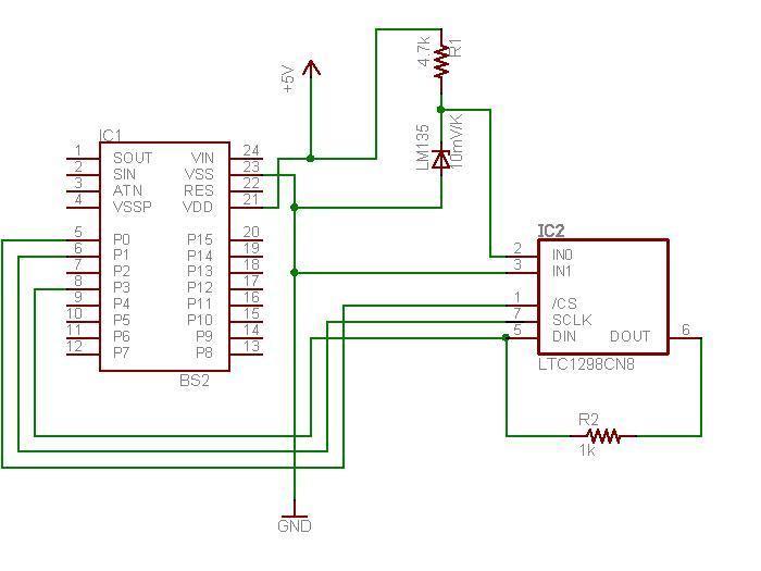
The schematic diagram illustrates the temperature sensor that is set to be launched. The LM135 sensor, functioning as a Zener diode, is connected via a foot-long cord to the circuit through a plug. This design allows the sensor to...
I decided to make a commercial surface mount PC board using the LED2 sensor concept. It is quite sensitive and can track to a few degrees of accuracy in bright sunlight. If a blocking shadow is used the accuracy...

No electrical contact exists between the circuit and the conductor. The 7474 flip-flop is triggered by the output from the Hall sensor, op amp, and Schmitt trigger. This triggering activates the optocoupler, turns on the triac, and trips the...