
oxygen sensor tester circuit board
Testing Procedure: To test the circuit, connect a 12V supply to the positive wire and ground the negative wire. Simultaneously, connect a variable supply of 0 to 1V to the sensor input, ensuring the negative wire is also grounded. The LEDs will illuminate based on the variable voltage applied to the circuit.
Faults: The initial attempt at constructing this circuit encountered several issues. The three diodes lacked drillings beneath them, causing them to share a track. The yellow LED shorted after repeated insertion. Pins 10 and 13 were not properly connected, and pins 6 and 9 were also disconnected. A drill hole under the IC inadvertently separated pins 6 and 9, necessitating a jumper wire to reconnect them. A solder fault bridged two tracks, which was corrected by resoldering. Additionally, the red LED was installed incorrectly, with the cathode facing the wrong direction, which was rectified by repositioning it. Despite these faults, the circuit did not function correctly; the green LED illuminated but turned off at 0.1V, the yellow LED only lit slightly, and the red LED failed to activate. These mistakes provided valuable insights into potential issues and how to prevent them in future designs.
A redesigned Sensor Tester was constructed, addressing all previous errors. This new version functioned correctly from the outset, resulting in a clean and organized circuit board. The experience gained from the initial attempt proved beneficial in understanding and avoiding faults in subsequent designs.
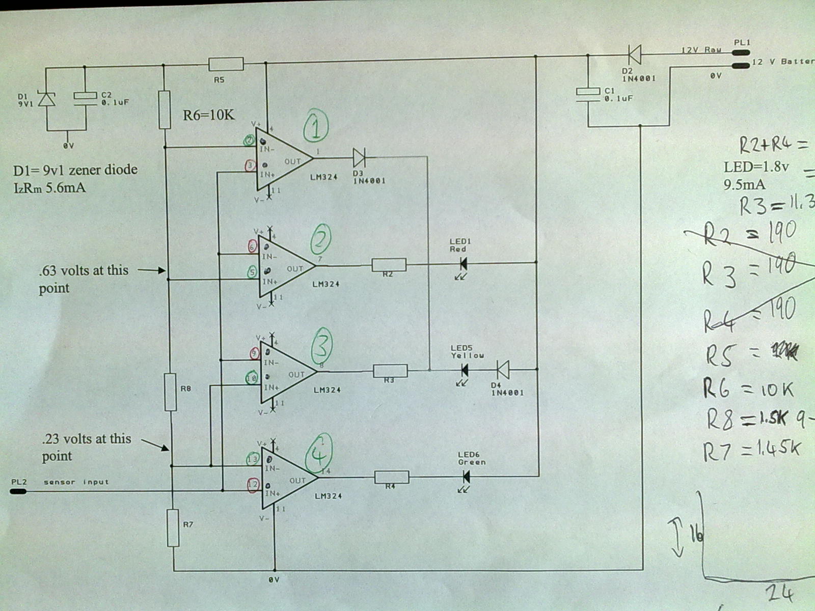
The circuit features a 12V supply connected to a capacitor and protection diode, ensuring a stable voltage for the IC. The zener diode configuration effectively regulates the output voltage to 9.1V, which is critical for the operation of the IC. The input sensor simulates various oxygen levels, activating different LEDs based on the voltage detected. The resistors R6, R7, and R8 play a crucial role in limiting the current to the IC and ensuring proper functionality. Grounding through R7 and pin 11 of the IC provides a stable reference point for voltage measurements. The LEDs serve as visual indicators of the oxygen sensor's output, allowing for easy monitoring during testing. The careful arrangement of components and thorough testing procedures contribute to the reliability and effectiveness of the Oxygen Sensor Tester circuit.A 12V supply is connected to the 12V positive wire, the current flows through a protection diode and a capacitor, in order to filter the voltage into a smoother flow. The zener resistor (R5) limits the current flowing to the zener diode, which regulates the voltage down to 9.
1 volts. Current for the various inputs of the Integrated Circuit is then further limited by the resistors R6, R7 and R8. Also 0V is connected to the negative lead which is connected to earth via R7 and the IC`s pin 11. After R5, pin 4 on the IC is connected to the 12V positive rail. The sensor input is connected to a supply of 0 to 1V which represents an actual oxygen sensor output range. A low voltage of 0. 01V will cause the red LED to light up, if a higher voltage of 0. 3V is detected by the oxygen sensor tester then the green LED will light up and when an even higher voltage of 0.
4 - 0. 5V is detected the yellow LED will light up, and finally when a high voltage of 0. 6 to 0. 9 is detected the red LED lights up. Testing Procedure: To test this circuit you will need to connect a 12V supply to the 12V positive wire and then the 0V negative wire to earth. At the same time a variable supply of 0 - 1V is to be connected to the supply wire, and again the earth to the 0V negative wire.
The LED`s will emit light in relation to the variable voltage you have placed upon the circuit. Faults: I had to make two attempts at this circuit. My first attempt taken had many faults come along with it. All three of my diodes did not have drillings under them as they ran along the same track. My yellow LED had shorted after multiple times of taking out and putting back in the LED. Pin 10 and 13 were not connected as they should have been, also Pins 6 and 9 were not connected. I put a drill hole under the Integrated Circuit (IC) which seperated pins 6 and 9 when I should not have, I then had to connect these two points by means of a jumper wire. One track was bridged to another due to a solder fault. I simply resoldered that point to remove the bridged connection made. My red LED was the wrong way round. My Cathode leg should have been facing toward the IC. This was easily replaced by taking out and placing the Cathode at the correct point. After all of these faults occured my circuit was still not running. My green LED lit up and then at 0. 1V it switched off and the yellow LED came on but only slightly. My red LED never lit up. All of these mistakes gave me a good understanding of what can be done to avoid these faults from occuring.
I began from scratch and redesigned a second Sensor Tester, taking into account all my faults and mistakes from before. I constructed my new Sensor Tester and it worked straight away with no faults. The need not to change any components resulted in a tidy finished board. Reflection: My first at this circuit resulted in a numerous amount of faults which in the end left me with a messy looking board.
Although my first attempt at this board was not useless, infact it was extremely helpful. My experience`s from my first Sensor Tester allowed me to identify the possible faults that were to occur, and also how to avoid them for next time. This was proven correct by my second attempt at this circuit where no faults were encountered and it made for a clean looking Oxygen Sensor Tester.
🔗 External reference
Related Circuits

Often, there is a need for an additional telephone ringer in an adjoining room to be alerted about incoming calls. For instance, if the telephone is situated in the drawing room, an extra ringer may be required in the...
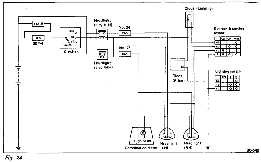
Understanding the headlight wiring in a car involves examining the purpose of two diodes in the circuit diagram. The circuit allows for two independent methods of activating the light relays: through the light switch or by flashing the high...

The relays in the AC arc welding machine manage the load through a three-way power circuit, as depicted in Figure 522. The selected relay type is KA, operating at 24V. Additionally, the time relay KT is of the JS7...
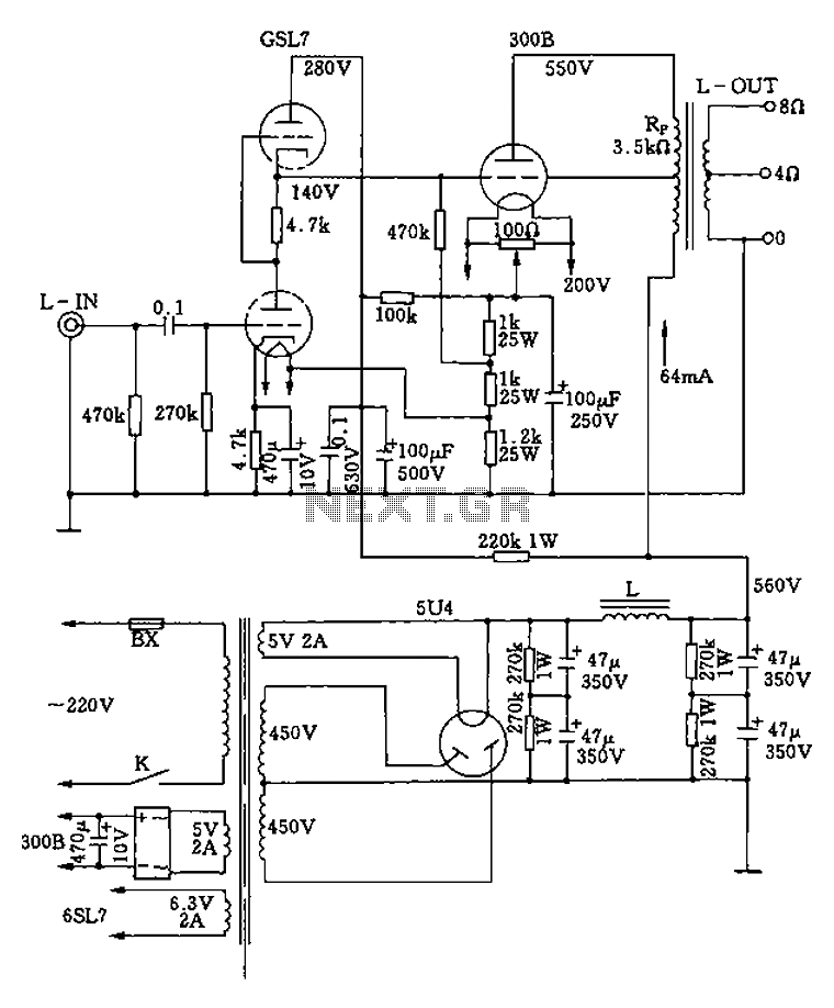
The 300B tube single-ended Class A amplifier circuit is as follows: The 300B tube single-ended Class A amplifier is a high-fidelity audio amplification circuit that utilizes a 300B vacuum tube as the primary amplification element. This design is characterized by...

This circuit dials a stored DTMF tone sequence from an EPROM when a control line is taken to 0 V. IC1 is a Schmitt trigger oscillator, operating at approximately 2 Hz. It clocks a 4024 binary counter. The outputs...
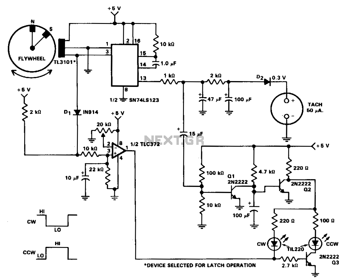
In machine and equipment design, certain applications necessitate the measurement of both shaft speed and direction of rotation. The circuit of a tachometer, which also indicates the direction of rotation, is illustrated. A flywheel is equipped with two magnets...
Warning: include(partials/cookie-banner.php): Failed to open stream: Permission denied in /var/www/html/nextgr/view-circuit.php on line 713
Warning: include(): Failed opening 'partials/cookie-banner.php' for inclusion (include_path='.:/usr/share/php') in /var/www/html/nextgr/view-circuit.php on line 713