
laser controller circuit

The CNC laser system's design emphasizes modularity and ease of maintenance. The integration of a power supply, solenoid-controlled gas lines, and cooling systems ensures efficient operation while maintaining safety protocols. The use of Gecko drives and the USC enhances the precision of the servo-driven table, allowing for intricate movements necessary for laser cutting and engraving applications. The inclusion of the JAM circuit serves a critical function in monitoring the operational states of the laser, ensuring that any drop in system performance is immediately addressed, thereby enhancing the safety and reliability of the operation.
The schematic, structured with the Eagle software, provides a clear representation of the interconnections among the various components, facilitating troubleshooting and future upgrades. The decision to use female headers for connections not only simplifies assembly but also allows for quick modifications without the need for extensive soldering. This design philosophy reflects a modern approach to electronic circuit design, prioritizing flexibility and user-friendliness. The PWM circuit's implementation ensures that the laser operates within optimal parameters, adjusting the output based on real-time feedback from the system.
Overall, the detailed planning and execution of this CNC laser controller project illustrate the complexities involved in modern electronic design, where multiple systems must work cohesively to achieve a common goal. The thoughtful integration of components and the strategic use of software to manage connections highlight the importance of a well-structured approach in electronic engineering.Development of the whole system required an exhaustive identification of all processes of the laser controller. I started with this diagram which outlines the major physical components that will be used for the cnc laser.
The laser has a power supply, a db-25 connector which reports various states of the laser, gas lines which are controlled by so lenoids, water flow and cooling systems, a servo driven CNC table, and a computer system for the central controlling unit. The servos are driven by Gecko drives, the Geckos are controlled by Jon Elson`s Universal Stepper Controller (USC).
There are an intimidating 50 or so I/O lines going into the control unit, so it was time to make another block diagram of all the internal electronic components. This picture was generated, which still leaves out items like indicator lights, power switches as well as the power supply that eventually was added to the circuit, but it was a good start.
The blocks marked JAM buzzer and PWM module were eventually combined into the custom circuit that was part of the project. Digi-key part numbers of most of the connectors were included in the drawing to help with intelligent ordering.
Ordering parts occurred over several iterations and while it`d be nice to put together a final BOM, one does not exist. The Gecko drives and the USC board are nice, but the laser controller also has some custom electronics that measure the states of laser itself, generate a pulse width modulated signal, and report an E-stop to the Unversal Stepper Controller.
The schematic of the custom electronics was generated using Eagle schematic software. The Eagle-formatted schematic can be downloaded here. You can try loading this big picture as well. The laser measurement was based on circuitry specified by the laser manufacturer (see figures 4-2 and 4-4). These circuits use differential line recievers and drivers. The states of the laser were fed into a "Just A Minute" or JAM circuit ( original schematic ). The JAM circuit was originally designed for a game show situation, where multiple contestants can hit a switch, when the switch is thrown a light goes on indicating who hit the button, and the rest of the contestants are locked out.
Perfect for my application, because if any of multiple states go low I want to register which system went low, lock out other inputs, and then flip the E-stop toggle of the USC board. The custom board also has a PWM circuit which is based on a 4541 programmable timer that feed into a binary counter and magnitude comparator combination.
There`s also a section on the circuit that debounces the push of a button and then toggles a D-type flip flop. This receives power from an unswitched power supply, when the user hits the pushbutton it turns on a solid state relay that powers up the remaining circuit.
The schematic epitomizes the I/O problem posed by the laser controller. There are over 120 different lines from connectors going to limit switches, encoders, geckos and the USC board. All lines were led into one of four 30 pin female headers. This was good way to go because it reduced any soldering or other types of direct connections between components - basically all connections between components were handled by linking between header pins using wire wrap.
This has several advantages: 1) it is an overall reduction in soldering - soldering is fine but its harder to disconnect - connections are made by crimping wires onto pins and then inserted into the header 2) The "logic" of how lines are linked is managed in software as described in the next section - this avoids mechanically looking at a header block from the geckos and deciding which wires have to be soldered to the pins leading to the encoders. 3) Overall, it reduces the spagetti of the circuit. Dont get me wrong, the spagetti is still there, but its centralized into four main headers. Readers may not want to go with this strategy, but 🔗 External reference
Related Circuits
As before, there are two sections: the transmitter board and the receiver board, both powered by a separate 9V battery or a fixed voltage power supply, depending on your needs. The transmitter board has an electret microphone module at...
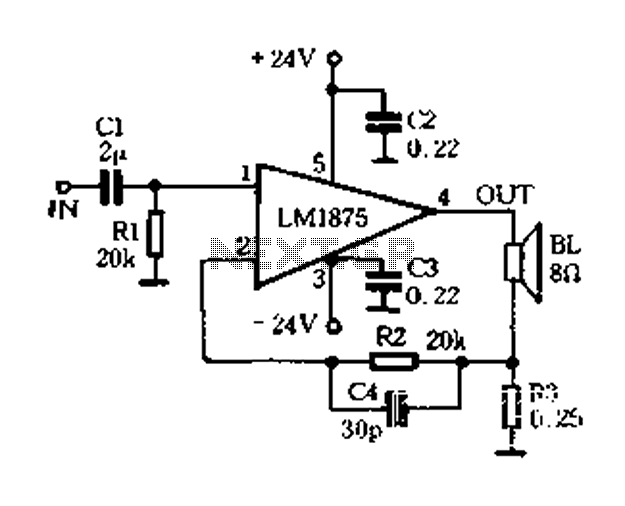
A current-sense amplifier is utilized to enhance the performance of the LM1875 current-mode amplifier circuit, as depicted in Figure 5-20. The resistor R3 and the series resistance of the speaker contribute to the current flowing through R3. This current...
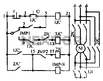
Motor windings are set to connect in a Y configuration while the load is active. The system includes an electric suction mechanism, and the motor is designed to operate under specific conditions. It is rated for 600 revolutions per...
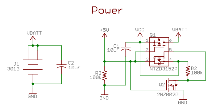
A two-diode selector circuit is utilized when the primary voltage source exceeds both the diodes' turn-on voltage and the input voltage of the second diode. Schottky diodes are preferred due to their low turn-on voltage (typically 0.4V) and high...
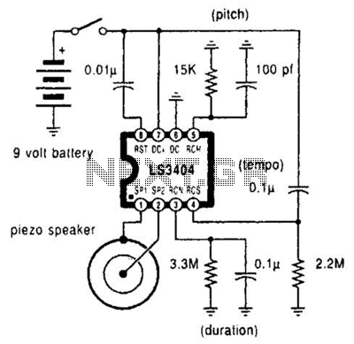
A high-quality melody circuit produces a slow decay waveform that generates chime-like notes. The pitch, tempo, and duration of the notes are all adjustable. The melody circuit is designed to offer a versatile sound generation capability, making it suitable for various...
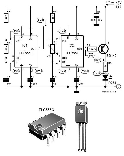
This infrared alarm barrier is designed to detect individuals passing through doorways, corridors, and small gates. The transmitter emits a beam of infrared light that is invisible to the human eye. When the light beam is interrupted by a...