
Infrared alarm barrier circuit

The infrared alarm barrier circuit operates by utilizing a transmitter and receiver configuration to ensure reliable detection of individuals. The transmitter's modulation scheme, which alternates the infrared light emission, is crucial for enhancing sensor responsiveness. The use of the TLC555 or TLC556 ICs allows for compact and efficient circuit design, while the adjustable components, such as the resistor R5 and preset P1, provide flexibility for different application requirements. The receiver circuit's design incorporates a rectifier to filter out unwanted modulation effects, ensuring that the system only responds to genuine interruptions in the infrared beam.
This alarm system can be effectively deployed in various settings, including security applications for homes, offices, and restricted access areas. Its robustness against ambient light interference makes it suitable for both indoor and outdoor environments, provided that appropriate shielding is applied in bright conditions. The simplicity of the circuit design allows for easy integration and maintenance, making it an ideal choice for users seeking a reliable and cost-effective solution for motion detection.This infrared alarm barrier can be used to detect persons passing through doorways, corridors and small gates. The transmitter emits a beam of infrared light which is invisible to the human eye. The buzzer at the output of the receiver is activated when the light beam is interrupted by a person passing through it.
The transmitter and receiver circ uits of the infrared alarm system shown here have been designed for a range of several meters, almost independent of ambient light conditions. Only in the rare case of the receiver sensor being exposed to bright, direct sunlight, some screening measures have to be added.
The transmitter does not emit a continuous infrared signal, Rather, it is modulated, that is, the 36-kHz carrier used to pulse the IRED (infrared emitting diode) on and off is itself switched on an off at a rate of about 300 Hz. The reason for doing so is that most infrared sensors, including the ones suggested in the diagram do not respond very well to continuous incidence of infrared light.
Switching the IR source off, even for a small period, allows IR detectors to recuperate`, and so optimise their ability to minimize the response to ambient light. The transmitter consists of two oscillators built around the ubiquitous 555 IC. Here, the current-saving CMOS version TLC555 (or 7555) is used. Alternatively, the two 555`s may be replaced by a single TLC556 (or 7556). IC1 is the 300-Hz generator, IC2, the 36-kHz source. The IRED type LD274 is pulsed at a relatively high peak current via driver transistor T1. If in your application the distance covered by the IR beam is relatively short, the value of resistor R5 may be increased to save on current consumption.
Preset P1 is adjusted for a carrier frequency of 36 kHz exactly (failing test equipment, adjust it for optimum range). The receiver is equally simple and also based on a CMOS 555. As long as the sensor picks up infrared light from the transmitter, the reset input of the 555 IC is held low and the buzzer is silent.
Components D1 and C2 act as a low-frequency rectifier to cancel the effect of the 300-Hz modulation on the transmitter signal. When the infrared light beam is interrupted, the oscillator built around the 555 is enabled and starts to produce a warning tone.
Finally, the test values indicated in the infrared barrier alarm circuit diagram are average dc levels measured with a DVM, under light/no light conditions. In fact, most test points carry rectangular or sawtooth waveforms. We aim to transmit more information by carrying articles. Please send us an E-mail to wanghuali@hqew. net within 15 days if we are involved in the problems of article content, copyright or other problems.
We will delete it soon. 🔗 External reference
Related Circuits
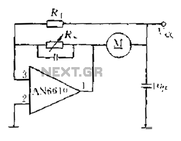
AN6610 Application Circuit operates as follows: When the supply voltage (Vcc) changes due to mechanical load variations, it can affect the motor speed. The motor speed is proportional to the back electromotive force (EMF). Consequently, the voltage across the...
The LM35 from National Semiconductor is a precision centigrade temperature sensor that provides an analog output voltage. It operates within a temperature range of -55°C to +150°C and has an accuracy of ±0.5°C. The output voltage corresponds to 10mV...

Dual adjustable power supply circuit with a diagram using IC LM317 and LM337. This variable power supply circuit has a range of 1.2 volts to 30 volts. The dual adjustable power supply circuit utilizes the LM317 and LM337 voltage regulators...

Using this low-cost project one can reproduce audio from TV without disturbing others. It does not use any wire connection between TV and headphones. In place of a pair of wires, it uses invisible infrared light to transmit audio...

This car headlight alarm circuit can be configured for one or two functions: First, it indicates that the headlights (or the side lights) should be turned off after the ignition is switched off. With this circuit, there should be...
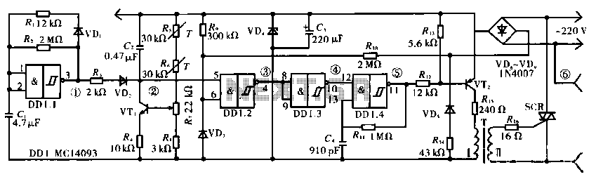
The circuit operates using a temperature stabilizer derived from the main oscillator (DD1.1), along with components including C1, R1, R2, and VD1. It incorporates a monostable multivibrator formed by R3, VD2, VT1, C2, R4, DD1.2, R7, and R8, as...
Warning: include(partials/cookie-banner.php): Failed to open stream: Permission denied in /var/www/html/nextgr/view-circuit.php on line 713
Warning: include(): Failed opening 'partials/cookie-banner.php' for inclusion (include_path='.:/usr/share/php') in /var/www/html/nextgr/view-circuit.php on line 713