
Laser Diode Circuit

The laser diode operates under specific electrical parameters that must be adhered to for optimal performance. The LM317 voltage regulator is pivotal in maintaining the required current levels while preventing damage to the diode. The heat sink is integral in managing the thermal load generated during operation, particularly when there is a significant difference between the input and output voltages. It is essential to calculate the appropriate resistor values to ensure the laser diode receives the correct voltage and current. Using the LM317 Voltage and Resistor Calculator can aid in this process by providing the necessary resistor values based on the desired output voltage.
In practical applications, it is advisable to verify the actual current flowing through the circuit using a multimeter, particularly when setting up the circuit for the first time. This ensures that the current is within the specified limits for the diode and prevents accidental damage. The use of a potentiometer allows for fine-tuning of the brightness, providing flexibility in applications where adjustable light intensity is required. It is also essential to consider the specifications in the laser diode's datasheet, which provides critical information on the maximum ratings and operational parameters to ensure reliability and longevity of the device. Overall, careful attention to the design and implementation of the driver circuit will lead to successful operation of the laser diode in various applications.Unlike LED light, a laser`s light output is more concentrated, meaning it has a smaller and more narrow viewing angle. This means it must be directed at its source more directly in order to be picked up. Laser light is also monochromatic, meaning laser light isn`t composed of several lights combined together, but one light of the same wavelength a
nd energy. Normally with LEDs, the different light outputs are based upon different colors combined. One such example is green light. To output green light, blue and yellow lights are combined to give green. Lasers, for the most part, do not follow this. Laser lights have a single spectral color and is almost the purest monochromatic light available. Laser diodes are used in CD players, CD-ROM drives, and other optical storage drives. They are used in laser printers, laser fax machines, laser pointers, measurement equipment, bar-code and UPC scanners, and in high-performance imagers, as well as various other applications. These are just the most popular and used aspects of them. A driver circuit is a circuit which can limit appropriately the amount of current being fed into the laser diode, so that it can function correctly.
Too much current and the laser diode will blow. Too little current and the laser diode will not have sufficient power to turn on and operate. Therefore, a driver circuit is needed to give precisely the correct range of current needed so that our diode will operate. The type of regulator we will use is the LM317 adjustable voltage regulator. The reason we need a heat sink is to dissipate excess heat created by the regulator. For example, if we input 6V into the regulator and it only regulators out 3V, this means that 6V-3V= 3V is dissipated as heat energy.
To safely get rid of this excess heat energy, we connect the voltage regulator to a heat sink so that the excess heat dissipates into the air rather than damage sensitive electronic components. For our input DC voltage, we can use anywhere from 5V-6V as our DC input. With a heatsink, even more voltage can be used such as up to 9V, since the heatsink will ensure that the difference in input and output voltage will be safely dissipated away as heat.
For this DC input, we can either use a DC power supply and set it to output 5V or we can use 4 `AA` batteries for 6V input or a 9V battery if used with a heatsink. The first capacitor, the 0. 1G‚ µF ceramic capacitor, serves to filter out high-frequency noise from the DC power supply. The second capacitor, the 1G‚ µF electrolytic, serves as a power load balancer to smooth out fluctuating signals.
The 2 resistors R will output approximately 2. 8V. So a 300G resistor will be perfect for our application for demonstration purposes. Later on, you can swap out this resistor for a potentiometer to vary the laser diode voltage to increase the brightness or dim it, as to how desired. However, if you are using a different laser diode, it may have different voltage and current requirements.
To calculatoe the output voltage needed output from the LM317 regulator, see the LM317 Voltage and Resistor Calculator. This calculator can find the R Just so that you can see the operating requirements of the laser diode, these are snippets of the datasheet.
If you want to see the PDF of the datasheet, click on the datasheet link below. To check the current flowing through the circuit, you an take a multimeter and place it in the DC ammeter setting. Break the circuit opening right at the anode of the laser diode and the anode of the capacitor and measure the amount of current flowing through.
At least 20mA is needed for the laser diode to turn on. This is called the threshold current; it again represents the minimum amount of current needed for the diode to function. However, more typically, the operating current is used for a decent amount of power output. For this diode, the typical operating current is 40mA. So 40mA should be fed. To increase or decrease resistance, you can change the value of resistance R. Increasing this resistance value increases current. Conversely, decreasing this value decreases current. The maximum amount of current which the laser diode should receive is specified by its maximum operating current, which in with this diode is 60mA.
No more than 60mA should be fed into the diode or the diode may be destroyed. So make sure to always follow the datasheet specifications. 🔗 External reference
Related Circuits
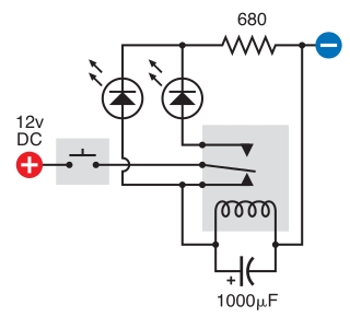
The intended result is for the relay to oscillate and the LEDs to flash when the button is pressed. However, when the button is pressed, the leftmost LED lights constantly, and nothing else happens. There is voltage across the...
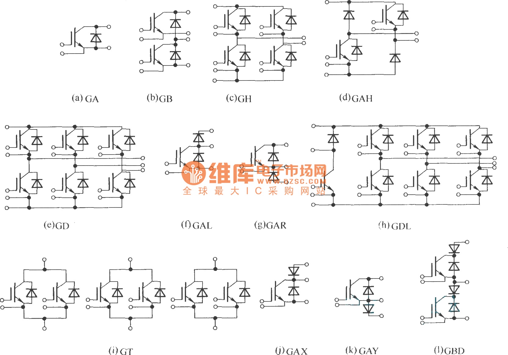
This document describes various electronic modules, including: (a) a single switch module; (b) a two-unit half bridge module; (c) an H bridge (single-phase bridge) module; (d) an asymmetrical H bridge module; (e) a three-phase bridge (six-unit or inverter bridge)...
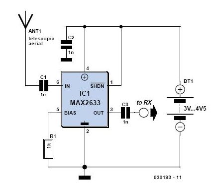
This is a preselector circuit designed for shortwave (SW) receivers, specifically a do-it-yourself (DIY) high-frequency preselector. The circuit employs a modern low-capacitance MOSFET with two gates, which generates a negative inverse reaction through an uncoupled source resistor. When applied...
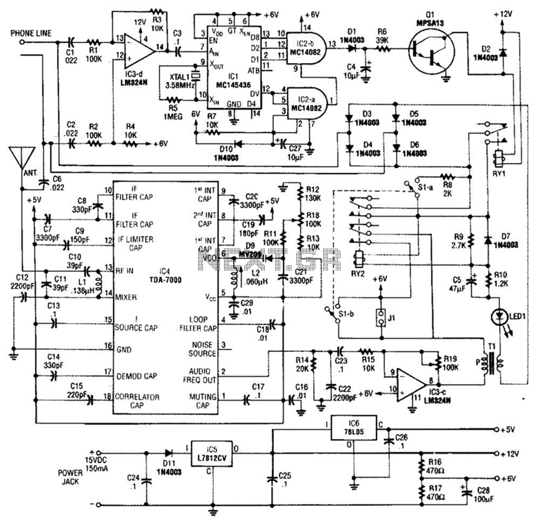
When the asterisk (*) is pressed on the touch-tone phone, a DTMF decoder, referred to as TCI, manages the on-hold logic. Audio from the FM receiver IC4 is transmitted over the telephone line when a hold condition is active....
Adrian Bontenbal has provided updated notes from his experiments in recreating Clara Rockmore's theremin. Bob Moog shared his hand-drawn schematic for Clara's instrument over a decade ago. Adrian started with that schematic to build his own Rockmore theremin. During...

This is a simple yet effective charger for lead-acid batteries. It utilizes a 12-volt car bulb as both a current regulator and a charge status indicator. The described circuit is an innovative approach to charging lead-acid batteries. It employs...