
relay circuit
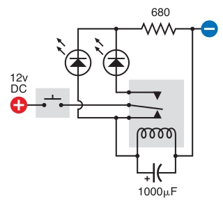
The circuit design involves a relay, a pair of LEDs, a resistor, a capacitor, and a push button switch. The relay serves as an electromechanical switch that controls the flow of current to the LEDs based on the button's state. When the button is pressed, it should close the circuit, allowing current to flow through the relay and energizing the coil, thereby activating the relay. The capacitor is placed in parallel with the relay coil to create a timing effect, allowing the relay to oscillate. The normally closed (NC) contacts of the relay are used to route the power to the LEDs.
The LEDs should be connected in such a way that they flash in response to the relay's oscillation. The correct orientation of the LEDs is essential for proper operation; the anode must be connected to the positive voltage, while the cathode should be connected to the ground or the negative side of the circuit. The resistor limits the current flowing through the LEDs to prevent damage, and its value should be calculated based on the supply voltage and the forward voltage of the LEDs.
To troubleshoot the circuit, it is essential to verify that the relay is functioning correctly by applying power directly to the coil. If the relay operates as expected, the issue may lie in the button press mechanism or the connections to the LEDs. Ensuring that the breadboard connections are secure and that the correct components are being used is vital. Additionally, confirming that the relay is indeed a double throw model is necessary, as using a single throw relay would not allow the intended oscillation effect.
In summary, the circuit requires careful attention to component orientation, correct pin usage, and verification of component functionality to achieve the desired oscillation of the relay and flashing of the LEDs.The intended result is that the relay oscillates and the LEDs flash when the button is pressed, however when I press the button the leftmost LED lights constantly and nothing else happens. I get voltage across the left LED, the resistor and the capacitor, but no voltage across the second LED and I can`t hear my relay oscillating.
There`s no sound from it. The stripboard drawing is some help, but is still not a schematic. For example, the stripboard drawing doesn`t show the polarities of the LEDs or the cap. Post a link to the site where you got the stripboard drawing. The stripboard drawing is some help, but is still not a schematic. For example, the stripboard drawing doesn`t show the polarities of the LEDs or the cap. Post a link to the site where you got the stripboard drawing. Since I`m getting voltage across my capacitor which is in parallel with the coil, does this mean there`s probably an issue with my relay and I should just get a new one Since I`m getting voltage across my capacitor which is in parallel with the coil, does this mean there`s probably an issue with my relay and I should just get a new one The relay should operate every time you apply power directly and release every time you remove power. If it does, then the coil of the relay is doing what it is supposed to. The next issue is to get the relay operating every time you press the button and releasing every time you release the button.
Run the power through the NC relay contacts, add the cap and the relay should oscillate when you hold down the button and stop when you release the button. Then, you can add the LEDs and get them to flash. The relay should operate every time you apply power directly and release every time you remove power.
If it does, then the coil of the relay is doing what it is supposed to. The next issue is to get the relay operating every time you press the button and releasing every time you release the button. Run the power through the NC relay contacts, add the cap and the relay should oscillate when you hold down the button and stop when you release the button.
Then, you can add the LEDs and get them to flash. I did the first thing you said about activating the relay with the switch and it wasn`t working, so I switched the wires from my 12vDC and it started working. I did the first thing you said about activating the relay with the switch and it wasn`t working, so I switched the wires from my 12vDC and it started working.
take your breadboard apart and start over. There aren`t a whole lot of things that could be wrong, mostly human error. make sure your LED polarity is correct and make sure you are working with 2 good leds. make sure you are using the correct pins on the relay. when I say "make sure, " I mean look at the datasheet and back at the component a few times and verify you have a correct understanding which pins are which. Also make sure that your relay is in fact a double throw model and not a single throw. You do this by comparing the model number to the model number breakdown in the datasheet. Sometimes they will make several models of relay all in the same package (look exactly the same), with the same pins, and some of the pins may not be functional.
take your breadboard apart and start over. There aren`t a whole lot of things that could be wrong, mostly human error. make sure your LED polarity is correct and make sure you are working with 2 good leds. make sure you are using the correct pins on the relay. when I say "make sure, " I mean look at the datasheet and back at the component a few times and verify you have a correct understanding which pins are which. Also make sure that your relay is in fact a double throw model and not a single throw. You do this by comparing the model number to the model number breakdown in the datasheet. Sometimes they will make several models of relay all in the same package (look exactly the same), with the same pins, and
🔗 External reference
Related Circuits
This digital DIY tachometer for bicycles utilizes two reed switches to gather speed information. The reed switches are positioned near the wheel rim, where permanent magnets, attached to the wheel spokes, pass by and activate the switches. The speed...
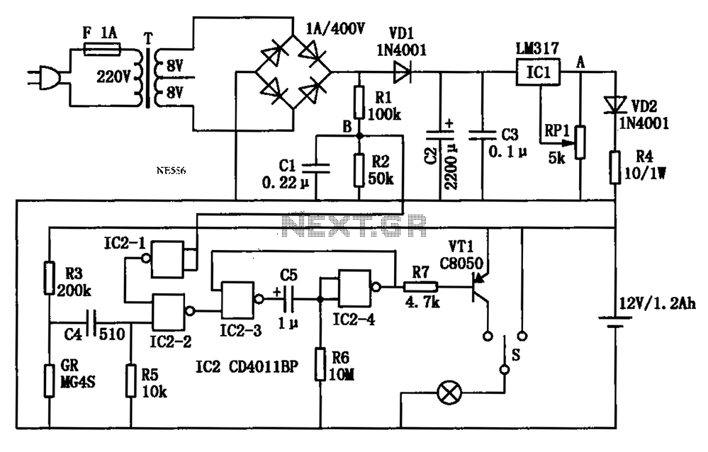
An automatic multipurpose emergency lights circuit is presented. Typically, emergency lights are connected to the mains for standby when fully charged. In the event of a sudden power failure, the ambient light transitions from strong to weak, indicating a...
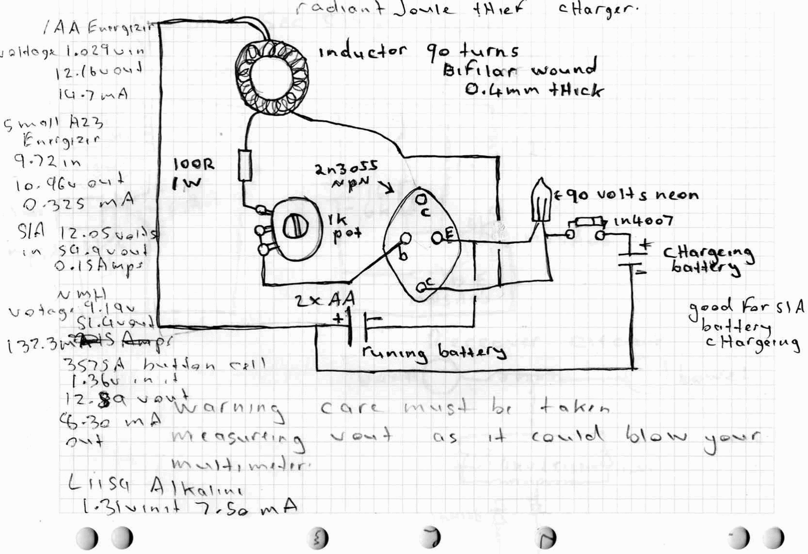
A high power joule thief circuit is explained in this post, which can be constructed by any new hobbyist. Here is the simplified drawing of the radiant joule thief battery charger. The inductor was wound with many turns until...
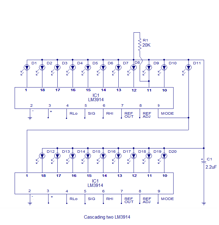
The core of this circuit is the LM3914 from National Semiconductor. The LM3914 is capable of sensing voltage levels and can drive a display of 10 LEDs in either dot mode or bar mode. The selection between bar mode...
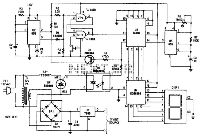
The electromagnetic ring launcher consists of four subcircuits: a clock circuit utilizing U5, a 555 oscillator/timer configured for astable operation; a countdown/display circuit incorporating U3, a 74190 synchronous up/down counter with BCD outputs set for countdown operation; U4, an...
This is a game timer circuit diagram. When the game timer is reset, two actions must occur: the 4017 counter must return to zero, and the 4060... The game timer circuit utilizes the 4017 decade counter and the 4060 binary...
Warning: include(partials/cookie-banner.php): Failed to open stream: Permission denied in /var/www/html/nextgr/view-circuit.php on line 713
Warning: include(): Failed opening 'partials/cookie-banner.php' for inclusion (include_path='.:/usr/share/php') in /var/www/html/nextgr/view-circuit.php on line 713