
Updated Circuit Details for Clara Rockmores Theremin

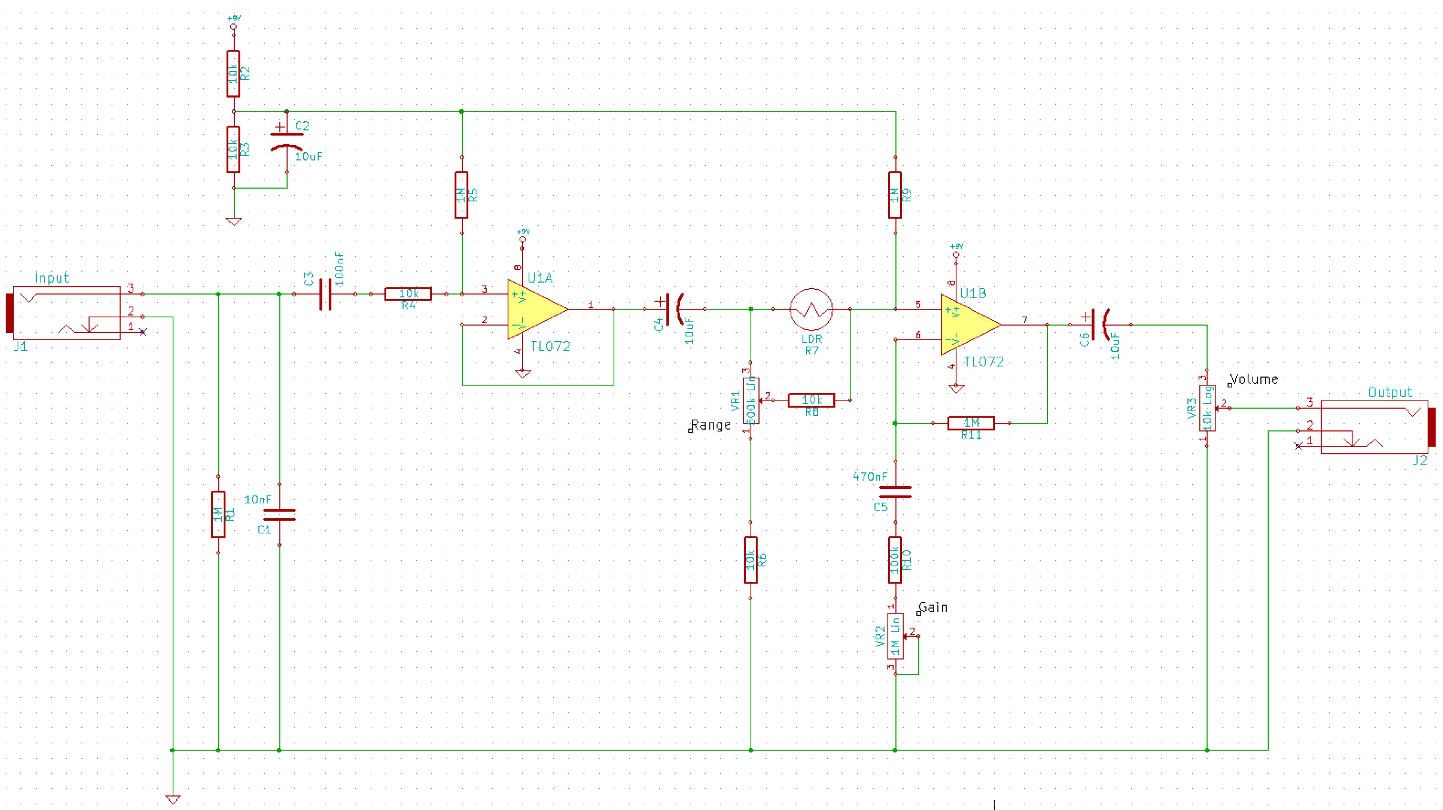
The recreated Rockmore theremin, based on Bob Moog's original schematic, serves as a testament to the enduring legacy of early electronic instruments. The design incorporates several key components that contribute to its unique sound and functionality. The timbre selection circuit allows the player to modify the tonal characteristics of the theremin, enabling a range of sound textures suitable for various musical styles. This circuit typically consists of a series of capacitors and resistors that can be switched in and out of the signal path, effectively altering the frequency response of the instrument.
The newly added tone decoder circuit is a significant enhancement, providing real-time feedback to the performer. This circuit utilizes a frequency detection algorithm to identify when the theremin is producing a tone at precisely 440Hz, which corresponds to the musical note A above middle C. This feature not only aids in tuning but also assists players in achieving desired pitch accuracy during performances. The implementation of this circuit may involve the use of a microcontroller or dedicated frequency detection IC, which processes the output signal from the theremin's oscillators.
Overall, the combination of these updated features—timbre selection and tone detection—offers a modern touch to the classic design of the theremin, making it more accessible and versatile for contemporary musicians. The adjustments made to component values further enhance the instrument's performance, ensuring that it meets the expectations of both novice and experienced players. This evolution of Clara Rockmore's theremin exemplifies the continuous innovation within the field of electronic music instruments.Adrian Bontenbal has provided us with updated notes from his experiments in building a re-creation of Clara Rockmore`s theremin. As you`ll recall, Bob Moog shared his hand-drawn schematic for Clara`s instrument over a decade ago. Adrian started with that schematic and built his own Rockmore theremin! Along the way, he ran into some snags and debugg ed some component values. Now, he`s back with more updates including a timbre selection circuit and a new tone decoder circuit that shows the player when they`re striking a perfect 440Hz tone. This sounds like a very useful feature to me - something I wish more theremins had built-in. 🔗 External reference
Related Circuits
Men particularly enjoy the convenience of television remote controls, often to the annoyance of their female partners. They tend to want to know what they are missing when the TV is tuned to a specific program, leading them to...

This circuit is a thyristor-based delay circuit known as a cut-off delay. It allows for a specified delay period after the thyristor is activated. The delay time of the circuit can be adjusted within 10 seconds by changing the...
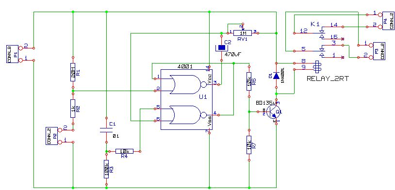
This is a simple alarm circuit using a CD4001 integrated circuit. It is designed for home, motorcycle, car, or other applications. The circuit will undergo computer simulation using Livewire, followed by printed circuit design with KiCad. SW1 is a...

This is an infrared emission circuit diagram. The NE555 circuit generates a 40 kHz pulse, which is sent by the infrared emission control SE303 after being amplified by VT. The remote receiver and infrared dimming circuit are composed of...

This generator circuit utilizes an overdriven amplifier to generate a 60 Hz square wave from the 60 Hz AC line. The circuit is suitable for line-operated applications as a clock source. The generator circuit operates by leveraging an overdriven amplifier...
This is a simplified schematic for the Solar Lifeforce. The design eliminates the expression/CV output features and the toggle for the buffer, making it a straightforward circuit. It may benefit from adding small capacitors between R5 and ground, as...