
using doorbell circuit control things radio control

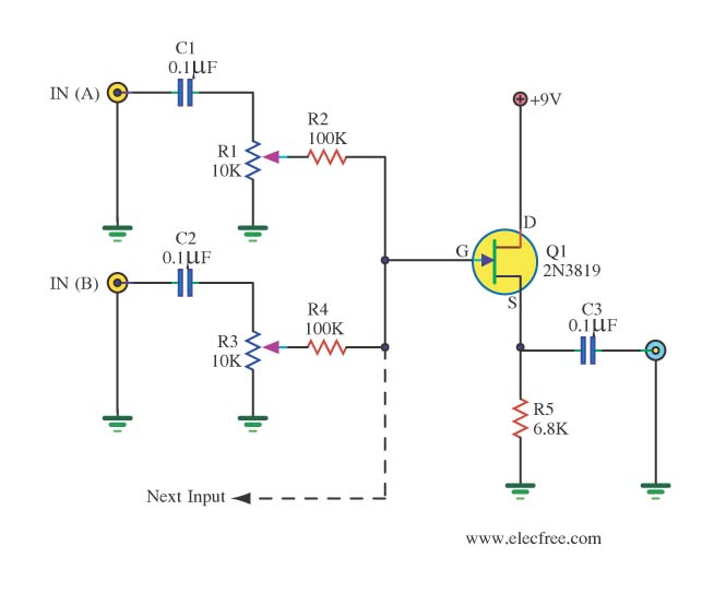
The described circuit functions as a remote-controlled relay latch and unlatch system, allowing a user to control a relay from any location within a house. The primary component of this design is a flip-flop circuit, which is a type of bistable multivibrator. This circuit will maintain a stable state until it receives an input signal to change its state.
When the button is pressed for the first time, it sends a signal to the flip-flop, causing it to change its output state to 'high'. This high state activates the relay, allowing current to flow to the connected load, thereby latching the relay. The relay remains in this state until the button is pressed again, at which point the flip-flop receives a second signal. This second signal changes the output state to 'low', cutting off the power to the relay and unlatching it.
The choice of using a MOSFET as a switch is advantageous due to its high efficiency and low power consumption characteristics. Unlike traditional relays, which require continuous power to keep their coils energized, a MOSFET can be switched on and off with minimal energy, thus conserving battery life. The control signal from the flip-flop can be used to gate the MOSFET, allowing for efficient control of the relay's power supply.
To implement this circuit, the following components are typically required: a flip-flop IC (such as the 74HC74), a relay rated for the load being controlled, a MOSFET capable of handling the relay's coil current, and a push-button switch for user input. Additional passive components like resistors and capacitors may be needed for biasing and debouncing the switch to ensure reliable operation.
Overall, this circuit design allows for convenient and energy-efficient control of electrical devices throughout a home, enhancing automation and user experience.Modify it to click and latch a relay when i press the button from any ware in the house. Also if it is somehow possible unlatch the relay when pressed again. Im sure you know what i mean. I was looking at it, all i think i have to do is create some sort of maybe, flip flip circuit (if i understand what they actually are correctly) so itwill take the first signal, and send it to the relay, which will latch somehow. then it waits for a second signal, that it will just cut the power to the relay, or unlatch it. Also, i thought about using a MOSFET as a switch, as it will conserve battery power that will be taken from energizing a relay coil for however long the circuit is active. 🔗 External reference
Related Circuits
The audio from each radio will be connected to the iPod audio output and vice versa. This setup alters the impedance and can affect sound levels, potentially damaging the audio circuits of one or more radios involved. It is...
In a servo system, the current drive connection is frequently utilized. The output current (IOUT) is proportional to the input channel number (y). Using the current drive mode can mitigate issues caused by the motor's large inductance, which induces...

The following circuit illustrates the Bedside Lamp Timer Circuit utilizing the CD4060 integrated circuit (IC). It operates for 30 minutes, with a blinking LED indicating the last 6 minutes of operation. The Bedside Lamp Timer Circuit is designed to provide...
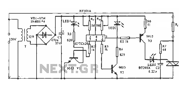
The circuit utilizes a built-in temperature sensor to control the triac TC620 for temperature regulation. The adjustment circuit consists of resistors Rp1 and Rn, which can be modified to set both the lower and upper temperature limits. LED1 illuminates...
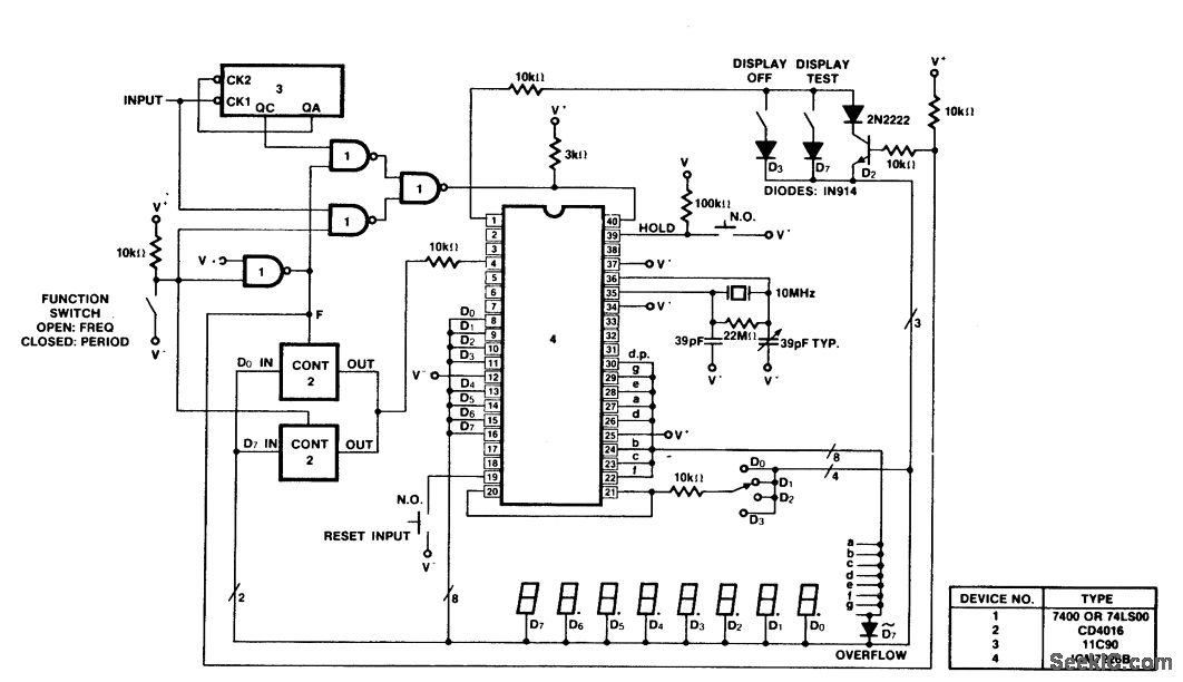
A 100 MHz frequency and period counter is constructed using the Intersil ICM7226B in a 40-pin DIP package. This circuit incorporates a CD4016 analog multiplexer to route the digital outputs back to the function input. The CD4016 operates as...
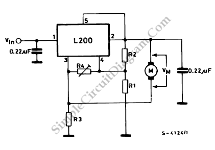
This diagram illustrates the usage of the L200 device for controlling the speed of permanent magnet motors. By utilizing resistors R1 and R2, the desired speed can be achieved. The L200 is a versatile integrated circuit designed for various applications,...