
Turbo Sound effect circuit for your non turbo car
The circuit schematic in question is designed to be simple and user-friendly, allowing for ease of understanding and implementation. This schematic typically includes essential components such as resistors, capacitors, diodes, and transistors, which are arranged to fulfill a specific function, such as amplification, switching, or signal processing.
In a basic circuit schematic, each component is represented by standardized symbols, ensuring clarity and consistency. The connections between these components are indicated by lines, which denote the flow of current. Power sources, such as batteries or power supplies, are usually included to provide the necessary voltage and current for the circuit's operation.
While specific details about assembly and testing are not included, it is crucial to follow best practices when working with electronic circuits. This includes verifying the schematic against the physical layout, ensuring proper component orientation, and utilizing appropriate tools for measuring voltage, current, and resistance during testing.
For individuals seeking to construct or analyze circuits, numerous instructional resources are available online, offering step-by-step guides, video tutorials, and community forums for troubleshooting and advice. These resources can significantly aid in understanding the practical aspects of circuit assembly and testing, complementing the straightforward nature of the schematic itself.The circuit schematic is straightforward, I`ll not try to give information about assembling and testing circuits, there should be lots of instructable.. 🔗 External reference
Related Circuits
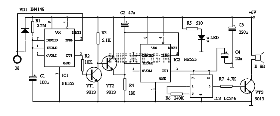
The circuit diagram illustrates a rotation sensor that activates a device, such as a motor or buzzer, when the circuit assembly is rotated. The design is based on the fundamental operation of a 555 timer. The rotation sensor circuit utilizes...
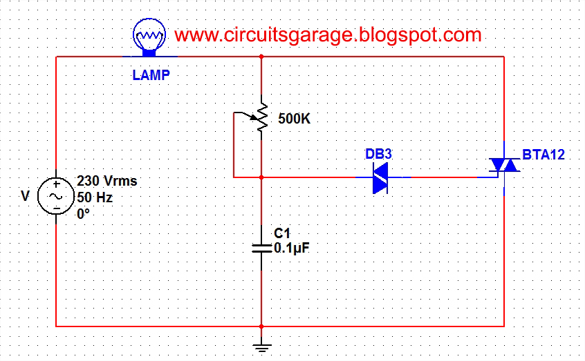
A light dimmer circuit is used to adjust the illumination of a lamp. The following circuit illustrates a basic TRIAC triggering circuit that utilizes a DIAC. In this circuit, the illumination of the light is regulated through the interaction...
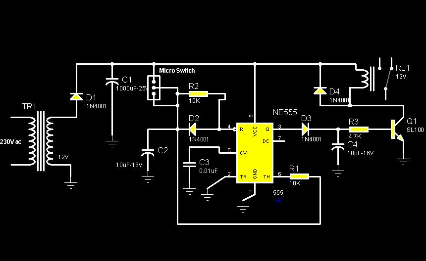
This circuit describes a door alarm system equipped with a time recognition feature. When the owner opens the door, it remains in a normal state for approximately 30 seconds without triggering the alarm. However, if the door is opened...
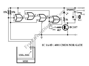
The circuit consists of a 555 timer IC configured as a multivibrator, which operates with two probes to measure the water level. When the capacitance between the probes indicates a high water level, the output from the 555 timer...

This circuit utilizes the Mitsubishi M65830 Digital Delay chip, which has proven to be simple and effective for applications requiring a fixed delay. The serial data necessary for achieving various delay settings is not readily available and would significantly...
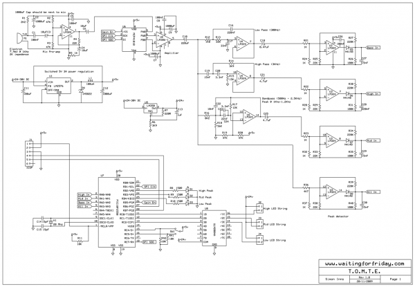
Most existing designs utilize direct switching of lights without any software control and include manual potentiometers for light sensitivity and overall gain settings. There are limited references regarding the frequency filter circuitry, explaining the specific frequencies the circuit is...