
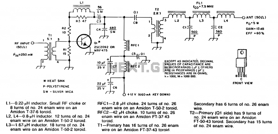
5W RF power amplifier
The circuit features a carefully organized layout designed for efficient integration onto a printed circuit board (PCB). The numbered components facilitate assembly and troubleshooting by providing clear identification for each part.
C5 and C8 are specified as disc ceramic capacitors, known for their stability and reliability in various applications. These capacitors are typically used in high-frequency circuits due to their low equivalent series resistance (ESR) and minimal inductance. The choice of ceramic capacitors helps in ensuring that the circuit maintains performance across a wide range of frequencies.
C6 and C7 are designated as tantalum or electrolytic capacitors. Tantalum capacitors are preferred for their high capacitance per volume and stable electrical characteristics, making them suitable for applications requiring compact size and high reliability. Alternatively, electrolytic capacitors may be used, which are generally larger but offer significant capacitance values. The selection between these types will depend on the specific voltage ratings and capacitance values required for the circuit operation.
Resistors R1, R2, and R3 are classified as 1/4 W carbon composition resistors. These resistors are known for their ability to handle transient voltages and provide reliable performance in various circuit conditions. Carbon composition resistors are often utilized in applications where high stability and low noise are essential.
The circuit design also includes the option to substitute silver-mica capacitors for polystyrene (P) types. Silver-mica capacitors are highly stable and exhibit low loss characteristics, making them suitable for high-frequency applications. This substitution allows for flexibility in component selection based on availability and specific performance requirements.
Impedance transformation ratios are indicated above transformers T1 and T2. These transformers play a crucial role in matching the impedance between different stages of the circuit, ensuring optimal power transfer and minimizing signal reflections. The transformation ratios can be critical in applications such as audio amplification, RF transmission, and other signal processing tasks, where impedance matching is essential for maintaining signal integrity.
Overall, this circuit design incorporates a variety of components selected for their specific electrical characteristics, ensuring reliable performance and adaptability in various electronic applications.Numbered components are so designated for PC-board layout purposes. C5 and C8 are disc ceramic. C6 and C7 are tantalum or electrolytic. Rl, R2 and R3 are Vi W carbon composition resistors. Silver-mica capacitors may be substituted for polystyrene (P) types. Impedance transformation ratios are shown above Tl and T2. 🔗 External reference
Related Circuits
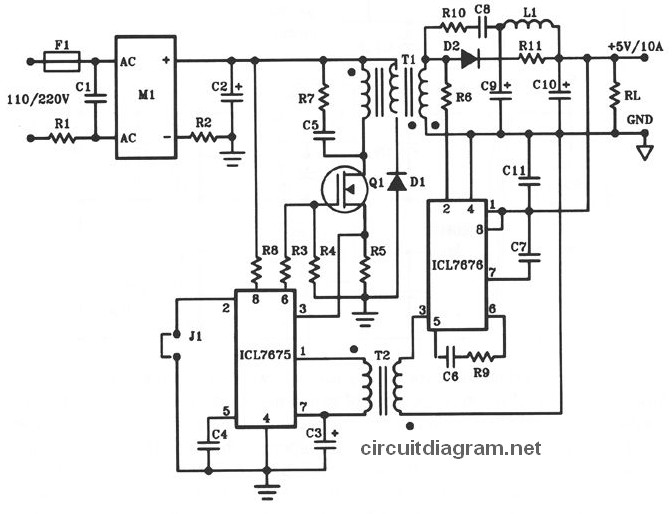
The following diagram illustrates the design of a 50W offline switching power supply circuit. This circuit is powered by a MOSFET, specifically the BUZ80A/IXTP4N8 for 220V AC input and the GE IRF823 for 110V AC input voltage. The output...
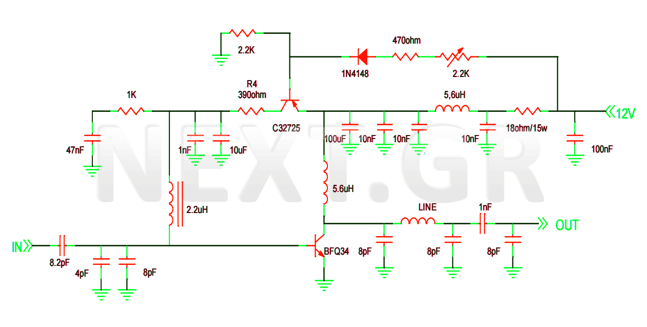
This project involves the construction of a VHF-UHF linear amplifier capable of operating at frequencies ranging from 47 MHz to 740 MHz. It serves as the final output stage for any transmitter functioning within these frequencies. The amplifier utilizes...
The three stages commonly found in audio amplifiers and operational amplifiers are clearly visible. However, actual audio designs often feature modifications and enhancements in key areas. This overview highlights design improvements in audio amplifiers, focusing on each of the...
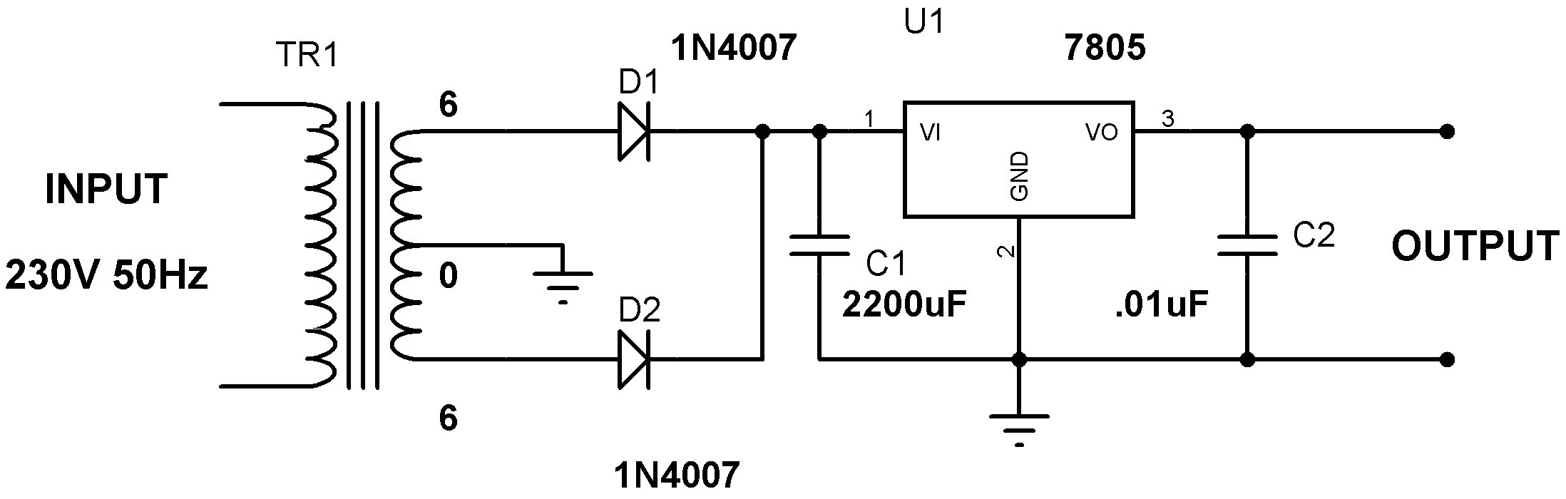
Designing a power supply requires careful consideration of each component. This discussion will focus on the design of a regulated 5V power supply. Note: Any transformer that provides a secondary peak voltage of up to 35V can be used;...
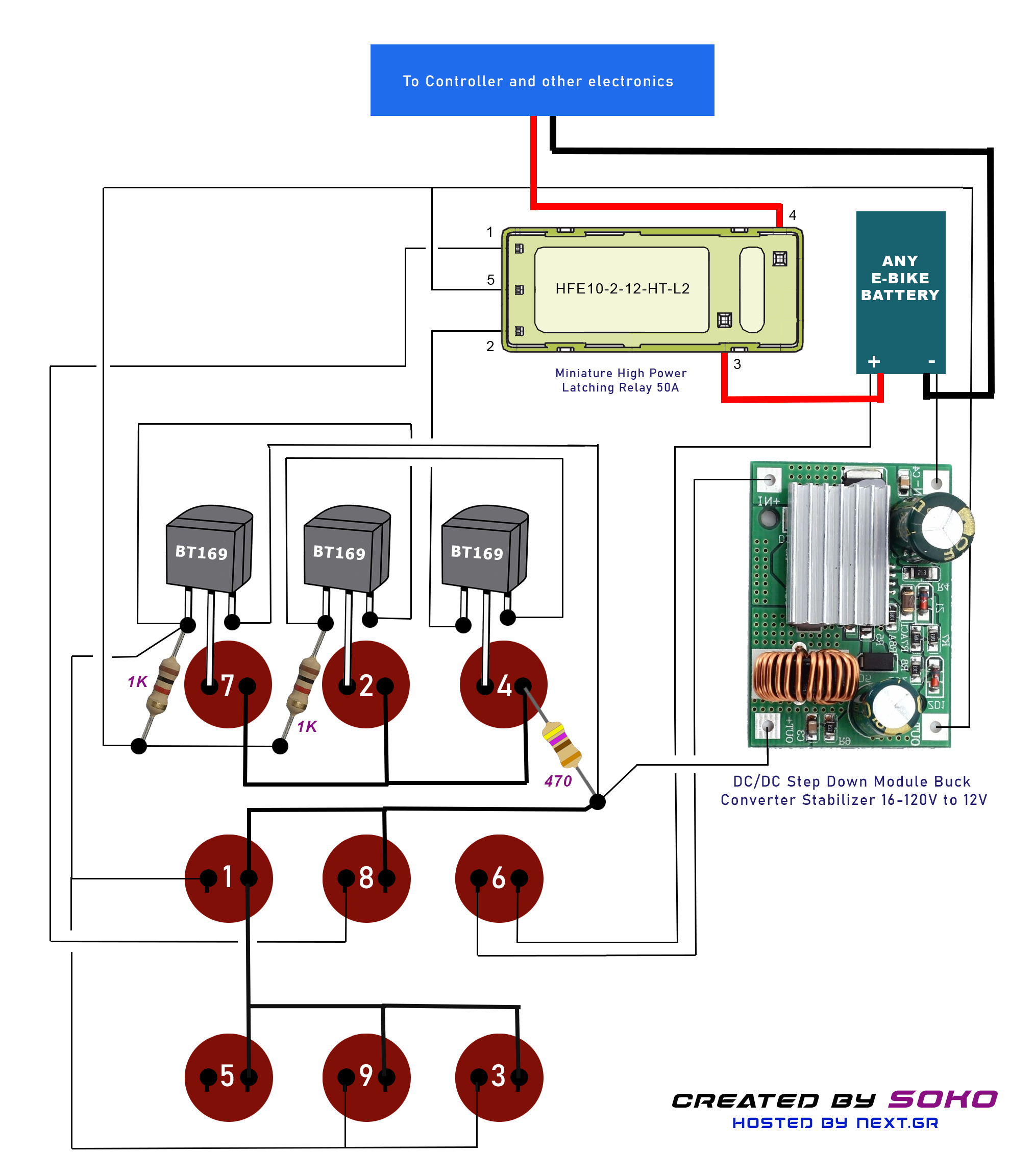
This project is designed for a custom-made battery casing that provides ample space for concealing components. The switch can be adapted for various projects but is specifically tailored to meet e-bike requirements. It utilizes a clever thyristor functionality to...
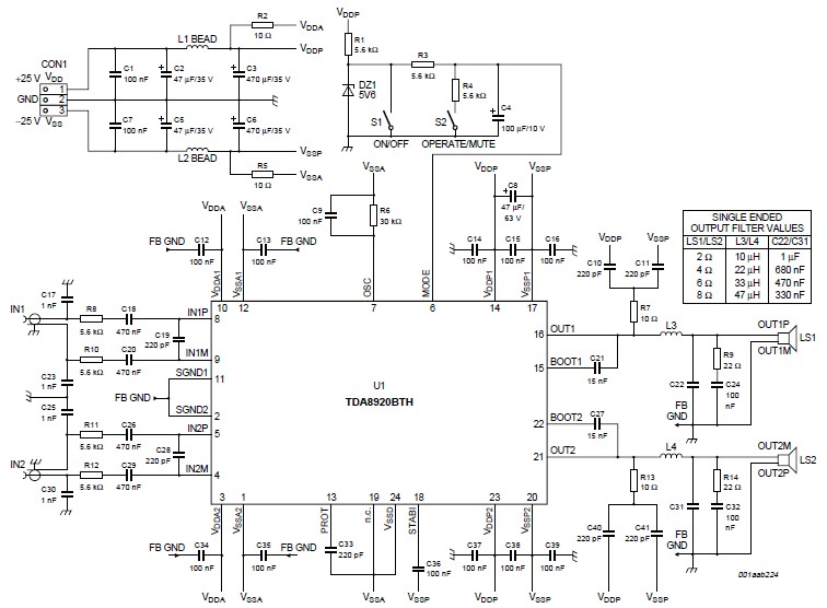
This high-power Class D audio amplifier electronic project is designed using the TDA8920BTH audio power amplifier IC. This power amplifier IC offers very high efficiency with minimal dissipation, yielding significant output power. The typical output power is 200 watts...