
Laser Target Finder circuit
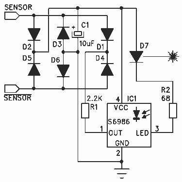
The circuit utilizes the Hamamatsu S6986 sensor, which is crucial for high-performance light detection applications. The design incorporates a bridge rectifier formed by diodes D2, D3, D5, and D6, which ensures that the sensor can be connected in either orientation, thus enhancing user convenience and flexibility. The bridge rectifier effectively converts AC voltage to DC, providing a stable power source for the sensor.
Capacitor C1 plays a vital role in filtering the power supply to the S6986, minimizing voltage fluctuations and ensuring that the sensor operates under optimal conditions. It is critical that C1 be placed in close proximity to the S6986 (IC1) to effectively bypass any high-frequency noise that may affect performance.
The S6986 sensor operates by emitting a laser beam at a 1/16 duty cycle. The photodiode integrated within the sensor is responsible for detecting the light reflected from the target. The internal processing circuitry of the S6986 compares the intensity of the emitted light to the intensity of the received light. This correlation allows for reliable detection of targets even in environments with significant ambient light interference.
When the S6986 detects a sufficient level of reflected light, its output signal transitions to a low level, indicating that the target is within the laser beam. Resistor R1 serves to limit the current flowing from the output of the S6986, protecting the downstream circuitry from excessive current that could potentially cause damage. The output from the S6986 is a boolean signal, providing a clear indication of whether the target is detected or not, facilitating straightforward integration into larger systems, such as an RCX sensor input.Thanks to the S6986, the circuit is very simple and requires few components. D2, D3, D5 and D6 forms a bridge rectifier allowing to plug the sensor connector brick in any direction. C1 filters power supply, it must be connected near to IC1 to bypass it properly. IC1 is the Hamamatsu S6986 sensor, the "heart" of this sensor. LED output drives the laser with a 1/16 duty cycle, and the included photodiode collects reflected light.
Internal processing circuitry correlates the received light to the emitted light, this enables very reliable detection even with high ambient light. When S6986 receives enough reflected light, its output goes to the low level (R1 limits the current), and the RCX sensor input becomes "true". Note that this sensor only returns a boolean value, "true" if the target is in laser beam, & 🔗 External reference
Related Circuits
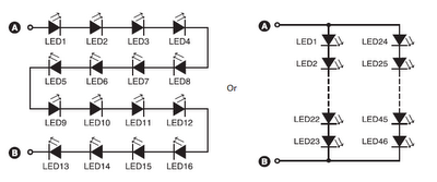
A series combination of 16 LEDs provides a luminance (lux) equivalent to a 12W bulb. However, if two series combinations of 23 LEDs are connected in parallel (totaling 46 LEDs), the output is equivalent to a 35W light bulb....
A newcomer to the forum is seeking assistance with DIY electronic circuits and lacks a formal background in electrical engineering. The inquiry indicates a desire to learn and engage with the community on topics related to DIY electronic circuits. For...
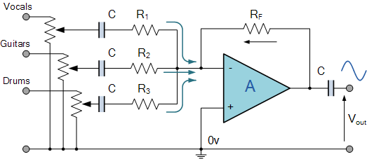
A program is needed to set the channels to their maximum level or to write the full scale to the Digital-to-Analog Converter (DAC). The MD schematics indicate that the audio signals are mixed with ratios of 0.0431 for the...
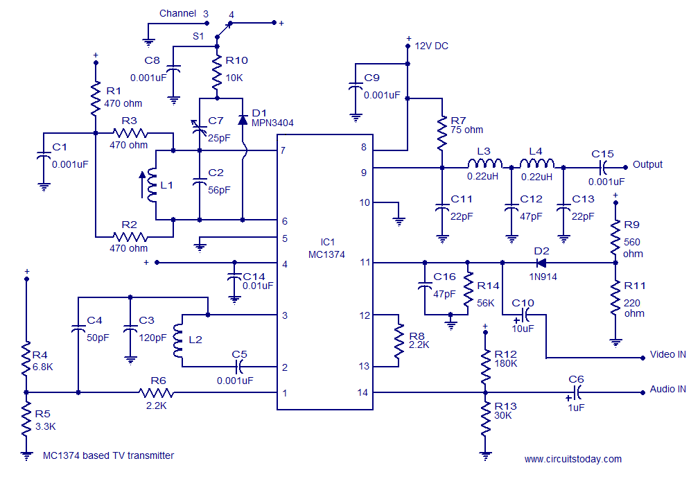
A simple TV transmitter circuit utilizing the TV modulator circuit IC MC1374. It operates with a 12V supply and is capable of broadcasting on channel 3 or 4, employing FM modulation for sound transmission. The TV transmitter circuit based on...
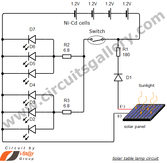
Solar energy has become a popular alternative for electricity production. This project focuses on teaching school students how to create solar lamps for their homes. The primary components of this simple solar lamp circuit include a small solar panel...
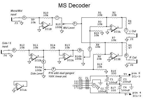
The schematic diagram of the MS Decoder may appear complex, but it is relatively straightforward. Initially, both the Mid and Side signals are buffered using unity gain inverting buffers, which are constructed around IC1b and IC2b. This buffering serves...