
MC1374 TV transmitter circuit

The TV transmitter circuit based on the MC1374 IC is designed to provide a straightforward solution for transmitting television signals. The MC1374 is a versatile modulator that supports frequency modulation (FM) for audio, making it suitable for transmitting sound alongside video signals.
The circuit requires a 12V power supply, which is essential for the operation of the MC1374 and its associated components. The choice of operating on channel 3 or 4 allows flexibility in compatibility with various television receivers, ensuring that the transmitted signal can be easily picked up by standard televisions.
The schematic typically includes the MC1374 IC, which is the heart of the circuit, connected to an RF output stage that amplifies the modulated signal before transmission. Additional components may include capacitors for filtering, resistors for biasing, and connectors for input and output signals. The FM modulation process involves encoding the audio signal onto the carrier wave, enabling clear sound transmission alongside the video.
To ensure optimal performance, careful attention must be paid to the layout of the circuit, minimizing interference and maintaining signal integrity. Antenna design is also crucial, as it directly influences the range and quality of the transmitted signal. A suitable antenna can enhance the reception quality on the receiving end, making the circuit effective for practical applications in broadcasting.
Overall, this simple TV transmitter circuit using the MC1374 IC provides an accessible means for enthusiasts and professionals alike to explore television transmission technology.Simple TV transmitter circuit using the TV modulator circuit IC MC1374. 12V supply, channel 3 or 4 operation, FM modulation for sound.. 🔗 External reference
Related Circuits
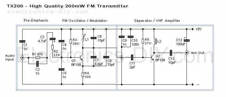
Here is the latest and greatly improved TX200 VFO/VCO FM transmitter. The most versatile transmitter to date that can be turned into high fidelity stereo PLL based 200mW FM transmitter. It is a perfect circuit for transmitting your music...
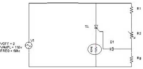
Simple resistor and diode combinations are used to trigger and control silicon-controlled rectifiers (SCRs) across the full 180-degree electrical range, exhibiting reliable performance at commercial temperatures. These circuits function optimally when SCRs possess relatively high gate sensitivities. In this...
The concept of a color organ involves the transformation of sound, including musical tones, into light. According to wave theory, both music and light possess similar wave characteristics. A color organ is an electronic device that visually represents sound through...

Continued from the previous post. The same principle is true for the following: temperature to current transmitter. In this case, the input voltage is proportional to the measured temperature, not the rotation. The temperature input is a full analog,...

This circuit for a laser door alarm operates on the principle of laser beam interruption. A low-cost laser pointer serves as the light source. When an object disrupts the laser beam, an alarm is triggered for a few seconds....
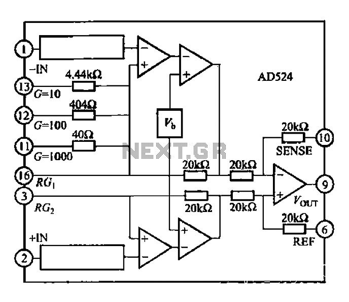
The AD524 is a low-drift instrumentation amplifier characterized by a drift voltage of 0.5 mV and a maximum drift of 25 mV at room temperature. It has low noise performance with a noise level of 0.3 mVp-p in the...