
16 led46 led circuit combination
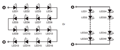
The described circuit utilizes LED technology to create efficient lighting solutions. The series configuration of 16 LEDs achieves an output comparable to a traditional 12W incandescent bulb, while the parallel configuration of 46 LEDs enhances luminance to that of a 35W bulb. The choice of LED arrangement is critical for achieving desired brightness levels, with series connections increasing voltage and parallel connections allowing for higher current capacities.
The rectification and smoothing components, specifically diode D1 (1N4007) and capacitor C1, are essential for converting the AC voltage to a stable DC voltage suitable for LED operation. The 1N4007 diode is a general-purpose rectifier capable of handling reverse voltages up to 1000V and forward currents of 1A, making it ideal for this application. Capacitor C1, which varies in value depending on the LED configuration, functions to filter out voltage ripples, ensuring a steady power supply to the LEDs.
For the 16-LED setup, a capacitor value of 22 µF rated at 100V is appropriate to provide necessary smoothing. In contrast, the 46-LED configuration requires a larger smoothing capacitor of 33 µF rated at 150V to accommodate the increased current demand. The use of zener diodes, rated at 48V and 69V for the respective configurations, provides voltage regulation, preventing overvoltage conditions that could damage the LEDs.
The cost range of Rs 200 to Rs 400 reflects the affordability of this lighting solution, making it an attractive option for consumers seeking energy-efficient alternatives to traditional lighting. Overall, this circuit design exemplifies the integration of modern electronic components to achieve high-performance lighting solutions with minimal energy consumption.Aseries combination of 16 LEDs Gives a luminance (lux) equivalent of a 12W bulb. But if you have two series combinations of 23 LEDs in parallel (Total 46 LEDs), it Gives equal to a 35W light bulb. Diode D1 (1N4007) and capacitor C1 act as rectifying and smoothing elements to Provide DC voltages to the row of LEDs.
For a 16-LED row, use Cx of 12:22 µF, 630V; C1 of 22 µF, 100V; and zener of 48V, 1W. Similarly, for 46 LEDs combination use Cx of 0:47 mF, 630V; C1 of 33 µF, 150V; and zener of 69V, 1W. This circuit (inclusive of LEDs) costs Rs 200 to Rs 400. 🔗 External reference
Related Circuits
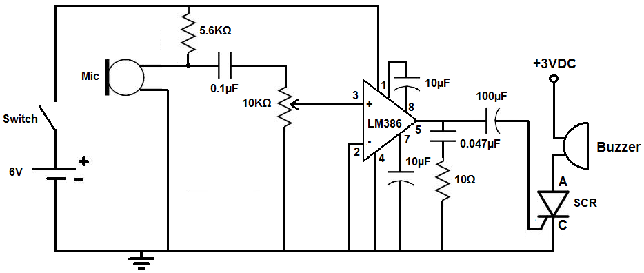
This circuit is designed to activate an alarm when it detects sound above a specified threshold. The alarm serves as a notification for any sound in areas that are typically quiet, such as quiet zones. Under normal quiet conditions,...
This circuit generates a two-tone effect similar to the cuckoo song. It can be utilized for doorbells or other applications due to its integrated audio amplifier and loudspeaker. When used as a sound effect generator, it can be connected...
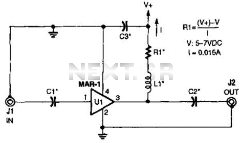
The low-cost Mini-Circuits MAR-X series of chips provides a significant advantage for RF builders, featuring inherent 50-ohm input and output impedances essential for RF systems. An MAR-1-based receiver/scanner preamplifier is illustrated. Capacitors Ci and C2 are chip capacitors, with...
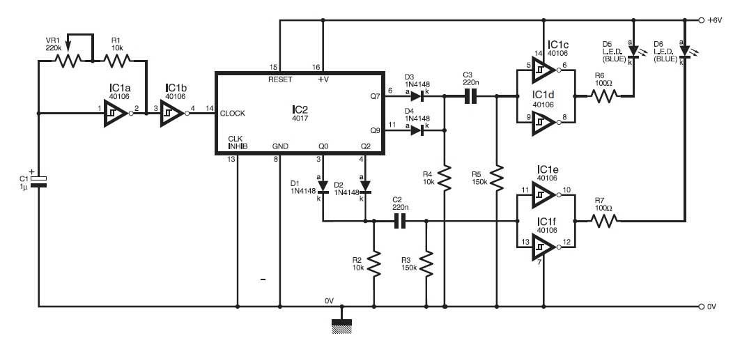
This circuit simulates the flashing lights of a police car, similar to those seen on British police vehicles. The operational amplifier IC1a functions as a square wave oscillator, with an adjustable frequency controlled by the variable resistor VR1 to...
The Wien-Bridge oscillator meets specific requirements due to the presence of a low-pass filter, a high-pass filter, and a 180-degree phase shift from the feedback networks connecting the input to the output. This configuration results in a total phase...
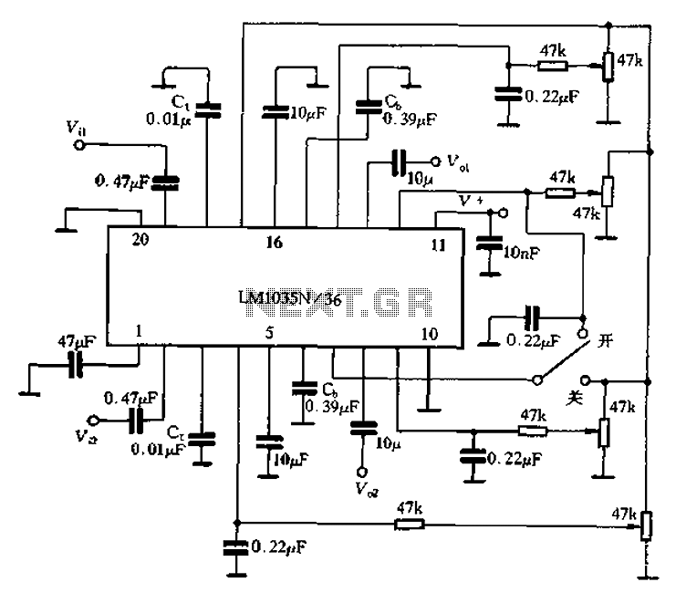
The circuit includes a loudness compensation control terminal at pin 7, which, when combined with the DC control voltage, forms a simple loudness compensation mechanism that enhances bass response. When the loudness control switch is in the OFF position,...