
Latching Water Sensor

The circuit employs a balanced Wheatstone bridge, which is a precise method for measuring unknown resistances. The bridge consists of four resistors arranged in a diamond shape. When the bridge is balanced, the voltage across the midpoints is zero, allowing for accurate measurement of resistance changes. In this application, the bridge output is connected to a JK flip-flop, which is a type of bistable multivibrator that can toggle its output state based on the input conditions.
The JK flip-flop is triggered by the output voltage from the Wheatstone bridge. The operational amplifier serves as an interface to amplify the small voltage changes from the bridge, ensuring that the flip-flop receives a clear and sufficient signal to change states. This amplification is crucial for achieving reliable operation, especially in applications where sensitivity is paramount.
The relay is driven by the output of the JK flip-flop, allowing for the control of higher power loads based on the state of the flip-flop. The relay acts as a switch that can open or close a circuit, making it suitable for various applications such as automation, control systems, or signal processing.
To enhance the circuit's sensitivity, resistors R1 through R4 can be adjusted. Increasing their resistance values will result in a more pronounced voltage change across the bridge for a given change in the measured resistance, thereby improving the overall responsiveness of the system. This adjustment is particularly beneficial in applications requiring high precision and sensitivity in detecting small variations in resistance.
Overall, this circuit design effectively integrates a Wheatstone bridge, JK flip-flop, operational amplifier, and relay to create a robust system for measuring and controlling electronic signals. A balanced Wheatstone bridge controls a JK flip-flop that uses an op amp as an interface. This in turn drives a relay circuit. Rl through R4 can be made larger for increased sensitivity.
Related Circuits

A decrease in the resistance of the CDS cell when light strikes it activates latch A and B, enabling tone oscillator C and D, which produces an output of about 1000 Hz. RA sets the trip level. SI resets...
Using LM134 and LM10 integrated circuits, a thermometer can be constructed with a sensing range of -55 to 150 °C. The ideal meter for this circuit is a 0-200 µA. The proposed thermometer circuit utilizes the LM134, a current source...
The general-purpose circuit of the simple pressure sensor alarm is constructed using a few easily accessible and inexpensive components. The operation of this circuit is straightforward. The simple pressure sensor alarm circuit typically includes a pressure sensor, an operational amplifier...
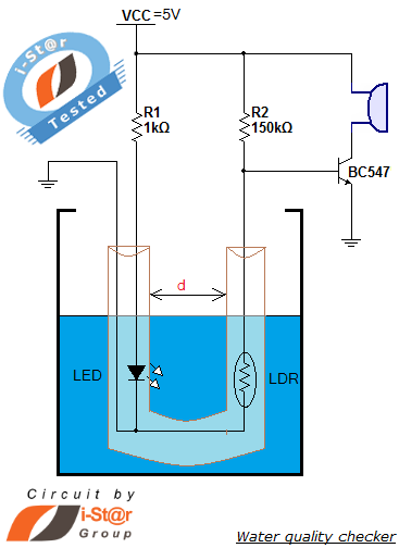
How to measure water purity and test water quality using a simple electronics project. Water purity measurement and water quality analysis can be performed using a water purity checker circuit. This circuit is constructed around a Light Dependent Resistor...
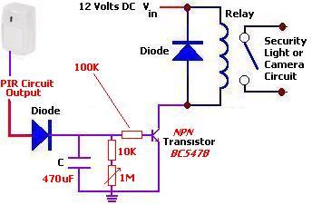
The following circuit illustrates a PIR Sensor Timer Circuit Diagram. Features include a simple design, enhanced accuracy, and efficiency. Components involved are a diode, among others. The PIR (Passive Infrared) Sensor Timer Circuit is designed to detect motion through infrared...
Interface the LCD with the 8051 microcontroller AT89S52. However, upon powering up the microcontroller, the LCD displays only black boxes. Multiple codes have been tried, but the output remains the same. The circuit has been simulated in Proteus, where...