
Layout Control Mother Board
The layout control motherboard serves as a central hub for managing various control and sensor functions within a model railway or similar layout system. The integration of a microcontroller facilitates communication and control over multiple components, significantly enhancing the user experience. Each control and sensor board can be independently designed and produced at a low cost, which promotes widespread adoption and customization among users.
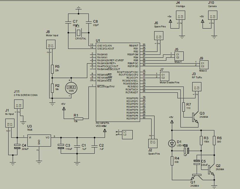
The interface circuitry, comprising the 74LS14 Hex Schmitt Trigger and the 74LS165 shift register, is essential for ensuring reliable signal processing and data management. The 7805 voltage regulator provides stable power, ensuring that all connected boards operate within their specified voltage range. The ability to control up to 32 LEDs allows for diverse applications, from simple indicators to complex lighting systems, all of which can be tailored to the specific needs of the layout.
Input handling is robust, accommodating a variety of sensor types while maintaining software debouncing for reliable operation. This flexibility allows for the integration of various user inputs, enhancing the interactivity of the layout. The 4-wire communication bus simplifies the connection between the microcontroller and the boards, while the shift register architecture allows for efficient data management, with the microcontroller being able to read and process data from multiple boards seamlessly.
The design considerations for the connectors, including the provision for wire loops for added security, reflect a practical approach to ensuring that the system remains robust in various operating environments. The absence of predefined dimensions for the control and sensor boards promotes creativity and innovation among users, allowing them to tailor their designs to fit specific requirements while adhering to the fundamental connectivity standards established by the motherboard.
Overall, the layout control motherboard represents a versatile and expandable solution for managing complex electronic layouts, providing both functionality and ease of use for hobbyists and professionals alike.The purpose of the layout control mother board is to provide a simple way to allow people to control portions of their layout. The layout control motherboard consists of a single microcontroller that interfaces to the MRNet bus and a number of slots into which inexpensive control and sensor boards can be plugged in.
All of the control and sensor b oards share the single microcontroller on the motherboard. The sensor and control boards that plug into the layout control mother board are meant to be quite inexpensive. The interface circuitry that must be on each control and sensor card consists of 1 74LS14 Hex Schmitt Trigger (Jameco 46640 @ $.
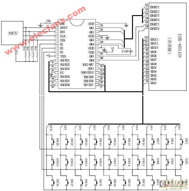
25 ea) and 1 74LS165 8-bit shift register (Jameco 46877 @ $. 49 ea). The motherboard provides regulated 5 volts to each board using a simple 7805 based power supply. In addition, the boards are provided unregulated positive and negative voltages that can be used to switch relays and the like. This control board provides a means to independently control up to 32 LED`s. The LED`s can be either simple ones or tri-color LED`s. This board should be useful for building a turnout control panel, lighting track-side signal lights, of lighting individual building lights.
This control board provides a means to sense up to 24 distinct inputs. These inputs can be buttons on a turnout control panel, turnout sensors, etc. Debouncing for SPST switches is done in software, whereas a DPST switch occupies two inputs. The controller talks to the control and sensor boards via a simple 4 wire bus. Each board implements a long shift register of 8-bit bytes. The output of control and sensor board is directed to the input of the next sensor board. The output of the last sensor board is automatically routed back to the microcontroller for reading. A simple clock line is used to shift the bits in all of the shift registers one bit over. Finally, there is a strobe line that is asserted by the microcontroller to indicate that it is done shifting data through the shift register. This strobe line is used to load data into and out of the shift register. 2-bits that identify the board. The value of 3 is specifically set aside for people who want to build a special purpose board that will only be used on their layout.
The shift register geometry on each control and sensor board is constrained to shift the indentification byte first, with the input bytes next, and finishing off with the output bytes. Finally, then case where both Inputs and Outputs are zero does not make any sense, so this case is reserved for future expansion of identifer space.
By encoding the number of input and output bytes into the board indentification byte, it is possible for the microcontroller software to easily figure out the total shift register length and were each board is in the total shift register. This means that new control and sensor boards can be introduced after without having to update the microcontroller firmware.
The current design of the mother board uses. 1 inch (2. 54mm) dual row male headers for connectors (Jameco 53479 @ $. 39 ea. ) Each sensor board must have one female right angle. 1" inch header to make the corresponding connection (Jameco 71829 @. $. 49 ea. ) The advatnage of these connectors is that they are quite standard and the are commonly available with gold plating. The disadvantage is that they do not have positive retention. To deal with the lack of positive retention, I have made it possible to add two little loops of wire next on each side of the female connector.
There are corresponding holes next to each male header on the mother board. A simple screw and nut can be used to firmly attach the control and sensor boards to the mother board. There are no predefined board dimensions for the control and sensor boards. The only requirement is that the female connector must be on the lower left of the board as shown below: There can be a large number of wire
🔗 External reference
Related Circuits
The project is developed by Team Stark, with Gilbert as the leader and team members Martin and Janssen. The tasks have been divided into three parts. The first part includes camera control, login database, installer, and network setup, which...

The LTC3722-1 and LTC3722-2 phase-shift PWM controllers offer all necessary control and protection functions for implementing a high-efficiency, zero voltage switched (ZVS), full bridge power converter. The adaptive ZVS circuitry delays the turn-on signals for each MOSFET, independent of...
The ET6201 is a LED display control drive circuit with a duty cycle of 1/7 to 1/8. It features 11 segment output gates and 1 segment/gate output, along with a display memory, control circuit, and key scanning circuit, which...
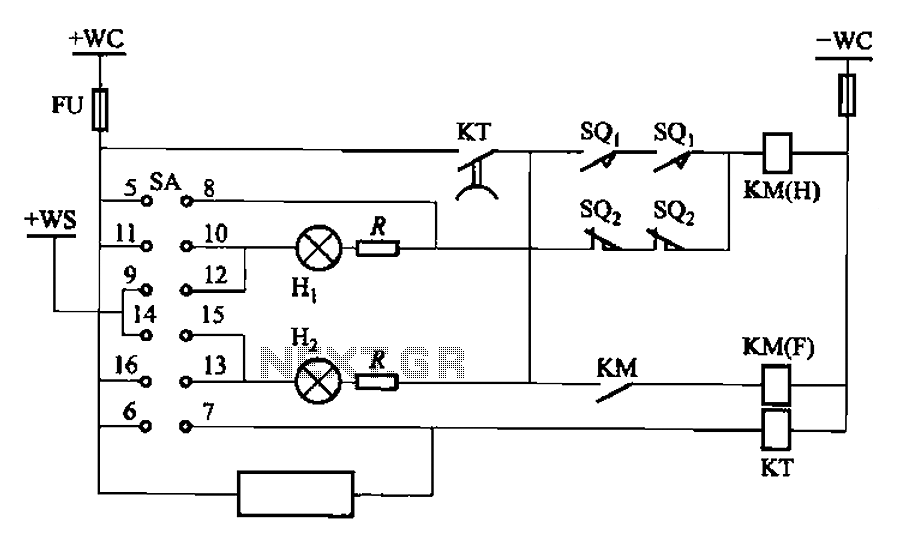
The BT9404 is a de-excitation type switch utilized with CJ4-S contactors and JT3-21/3-type electromagnetic relays. The control circuit is depicted in Figure 7-55. The KM contactors used are CJ4-S, while the time relay is the JT3-21/3. The SA component...
Industrial applications sometimes require that power be briefly applied to a load following the closure of a switch, such as a microswitch or foot switch. The load could be a heating element used for sealing plastic bags, a DC...

This article discusses a simple 5-channel radio remote control circuit utilizing the TX-2B and RX-2B integrated circuits from Silan Semiconductors. The TX-2B/RX-2B is a remote encoder-decoder pair suitable for remote control applications. It features five channels, a wide operating...
Warning: include(partials/cookie-banner.php): Failed to open stream: Permission denied in /var/www/html/nextgr/view-circuit.php on line 713
Warning: include(): Failed opening 'partials/cookie-banner.php' for inclusion (include_path='.:/usr/share/php') in /var/www/html/nextgr/view-circuit.php on line 713