
BT9404 type excitation switch control circuit

The BT9404 de-excitation type switch is designed to effectively manage the operation of CJ4-S contactors and JT3-21/3 electromagnetic relays in various electrical applications. The schematic representation of the control circuit, as illustrated in Figure 7-55, provides a comprehensive overview of the interconnections and functionalities of the components involved.
The CJ4-S contactors serve as the primary switching devices, responsible for controlling high-power circuits. They are designed to handle significant load currents and voltages, ensuring reliable operation in demanding environments. The JT3-21/3 time relay introduces a delay function, allowing for precise timing control in the switching operation. This feature is crucial in applications where sequential operation or time-based control is required.
The SA component plays a vital role in controlling the LW2-2-la switch, which is responsible for managing multiple outputs, indicated by the numbers 4, 6a, 40, and 20/F8. This switch configuration allows for flexible control over various circuits, enhancing the overall functionality of the system.
The inclusion of Hi and Hz indicators in green and red provides visual feedback on the operational status of the system, facilitating monitoring and diagnostics. The specifications of 11OV and 8W indicate the operational voltage and power consumption of the indicators, ensuring they are suitable for integration into the control circuit without overloading.
Furthermore, the additional resistance of 2.5kΩ is likely employed for current limiting or signal conditioning purposes, ensuring that the control signals remain within acceptable levels for the connected components. The SQ1 and SQ2 terminal switches are crucial for establishing connections within the circuit, allowing for the integration of external devices and enhancing the modularity of the system.
Overall, the BT9404 de-excitation switch, in conjunction with CJ4-S contactors and JT3-21/3 relays, forms a robust control circuit capable of managing complex electrical tasks with precision and reliability. BT9404 de-excitation type switch by the CJ4-S contactors and JT3-21/3-type electromagnetic relays. Its control circuit is shown in Figure 7-55. Figure, KM contactors CJ4-S; KT was time relay JT3-21/3; SA controls switch LW2-2-la, 4, 6a, 40, 20/F8; Hi, Hz green, red XD2, llov, 8W, additional resistance 2.5k0; SQi, SQ2 for the terminal switch.
Related Circuits
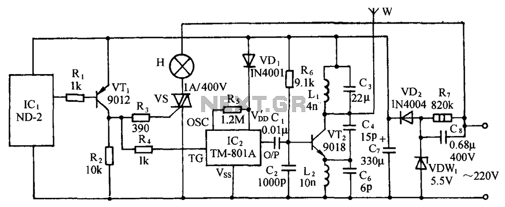
The circuit includes a comprehensive array of components such as vibration sensors, a follower, a lamp relay control circuit, a voice sounding circuit, a high-frequency oscillation circuit, and an AC rectifier buck power supply circuit. The vibration sensor is...
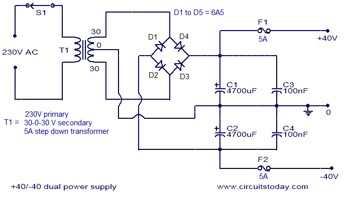
This is an economical 150 Watt amplifier circuit that utilizes two complementary Darlington power transistors, TIP 142 and TIP 147. It is capable of delivering a robust 150 W RMS to a 4 Ohm speaker, offering significant audio output....
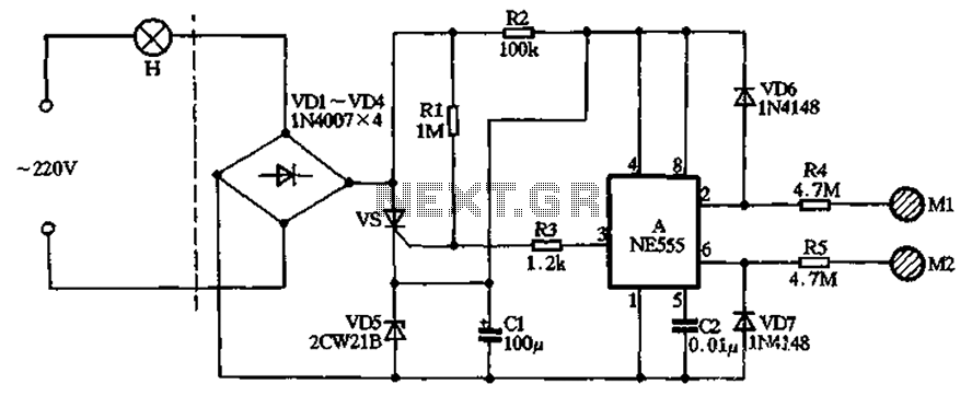
The circuit illustrated in the figure features a dashed line on the left, representing a standard lighting circuit, while the right side is responsible for the dual functionality of touch activation using the NE555 timer. Components VD1 through VD4...

A simple audio watt meter circuit or an audio power or audio level meter circuit with diagram and schematics to measure amplifier audio output power in watts. The audio watt meter circuit is designed to measure the output power of...
These two projects, Wah and Fuzz, are the results of a modification to a Morley dual channel volume control pedal that one of my sons suggested I undertake as he had no use for the volume unit but thought...
Microchip's PIC18F14K50 is an excellent choice, offering a wide range of features in a compact package at an affordable price. While focusing on the chip's numerous capabilities, a specific requirement for its flash programming was overlooked during the design...