
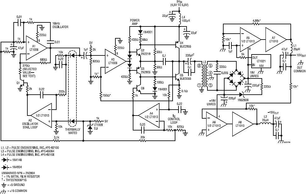
interleaving good boost converters too
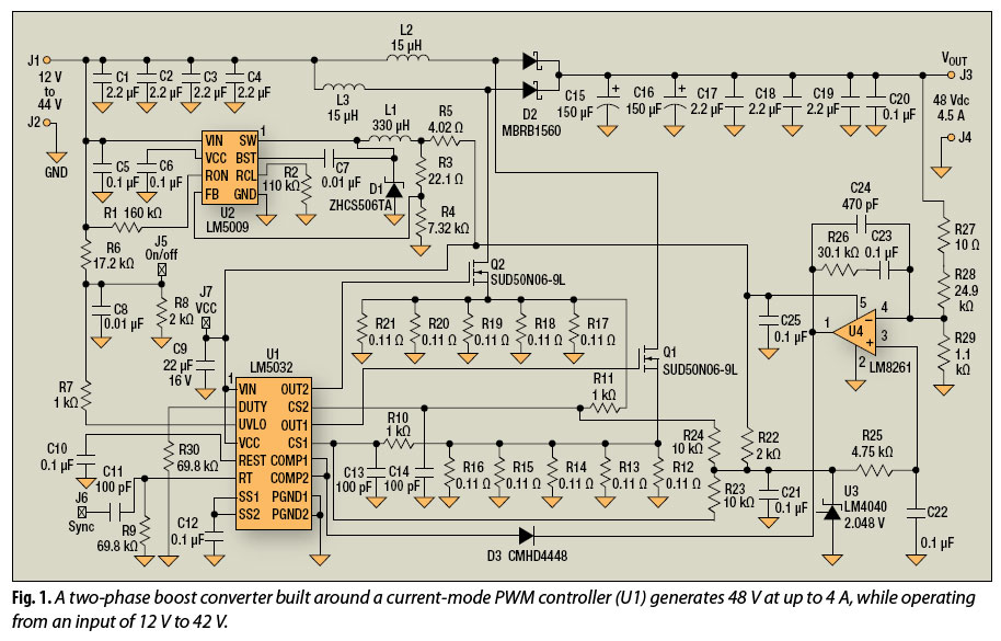
The multiphase technique involves the use of multiple phases in power conversion circuits, which allows for the distribution of current across several inductors and capacitors. This distribution leads to a reduction in the overall ripple voltage, as the output current is smoothed out over the multiple phases. In a typical multiphase boost converter, each phase operates in a synchronized manner, sharing the load equally, which results in lower stress on individual components and improved thermal performance.
By employing a multiphase topology, the size of passive components can be significantly reduced. Smaller inductors and capacitors can be used without compromising performance, as the effective current handling capability increases with the number of phases. This reduction in component size not only saves board space but also enhances the overall reliability of the circuit.
Furthermore, the multiphase approach can improve transient response. When there is a sudden change in load, the multiple phases can respond more quickly than a single-phase converter, ensuring stable output voltage and current. This characteristic is particularly beneficial in applications where load conditions fluctuate rapidly.
In summary, the multiphase approach is a valuable strategy in the design of boost converters, providing enhanced efficiency, reduced ripple, and smaller component sizes, while also improving transient response and overall circuit performance.Long used to improve efficiency, reduce ripple, and shrink capacitor and inductor size in buck converters, the multiphase approach can provide the same benefits for boost converters.. 🔗 External reference
Related Circuits
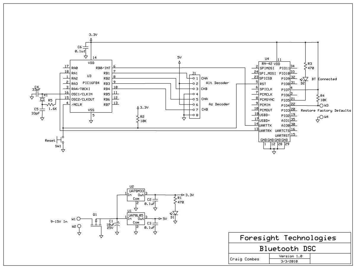
This variation of the Digital Setting Circles project was developed by Craig Combes, who shared his insights for others to replicate his version. Many users utilize Dave's serial DSC board along with a serial to Bluetooth adapter, which can...
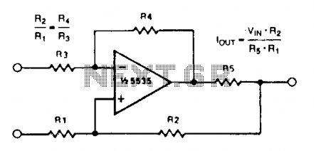
A simple voltage-to-current converter is illustrated. The output current is given by 0t or Vjn/R. For negative currents, a PNP transistor can be employed, and for improved accuracy, a Darlington pair can replace the transistor. With meticulous design, this...
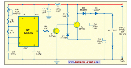
All miniature electronic devices operate off batteries. Some of them require higher than the standard battery voltages to function efficiently. Miniature electronic devices, which include a wide range of applications from portable gadgets to remote sensors, typically rely on battery...
This AM/FM antenna booster circuit amplifies the broadband signal from the antenna. This antenna booster is designed to work for FM, AM, and SW receivers. The AM/FM antenna booster circuit is an essential component for enhancing radio reception across...
Various sawtooth voltage generators utilize the principle of capacitor charging and discharging to produce sawtooth waveforms in both forward and reverse directions. A simple sawtooth voltage generator circuit is straightforward in design; however, it suffers from poor linearity in...
Many systems require that the primary source of DC power be converted to other voltages. Battery-driven circuitry is an obvious candidate. In many electronic applications, it is essential to convert a primary source of direct current (DC) power into various...