
LCD Caller ID with AT89C2051
The described project is a call tracking and display system suitable for various environments such as homes, shops, and offices. It is designed to monitor both incoming and outgoing calls, featuring a built-in Caller ID functionality. The system utilizes a Liquid Crystal Display (LCD) to visually present the incoming and dialed phone numbers, providing users with real-time information about their call activities.
The core component of this system is a microcontroller, which serves as the central processing unit. The microcontroller manages the entire operation of the system, including control over the LCD display and the DTMF (Dual Tone Multi-Frequency) decoder. The DTMF decoder is responsible for interpreting the tones generated by the telephone keypad when dialing a number, allowing the microcontroller to retrieve the dialed digits.
The integration of the microcontroller with the DTMF decoder enables the system to capture and process both incoming and outgoing call data efficiently. When a call is received, the Caller ID information is decoded and sent to the microcontroller, which then formats this data for display on the LCD. The LCD serves as the user interface, providing a clear and accessible means of viewing call information.
In terms of the schematic design, the microcontroller would be connected to the DTMF decoder through a series of digital input pins, allowing it to read the decoded signals. The LCD display would be interfaced using either a parallel or serial communication protocol, depending on the microcontroller's capabilities and the desired complexity of the design. Additionally, power supply considerations must be made to ensure stable operation of all components, with appropriate voltage regulation and filtering to minimize noise.
Overall, this project showcases a practical application of microcontroller technology in telecommunications, enhancing the ability to track and manage call information in real-time.This Project can be used in home, shops, offices etc. It keeps tracking of both Incoming and Outgoing Calls. It has a built in Caller ID. The incoming and the dialed numbers are displayed on the LCD display. The system will display the numbers over the LCD display. The Microcontroller is used to control the whole system it completely control the LCD display and the DTMF decoder. It gets the numbers through the DTMF decoder and display it over the LCD (Liquid Crystal Display). 🔗 External reference
Related Circuits
The following circuit illustrates the AD8531 integrated circuit used for the automatic control of LCD panel backlighting. Features include the ability to compensate for aging effects and other functionalities. The AD8531 is a precision operational amplifier known for its low...
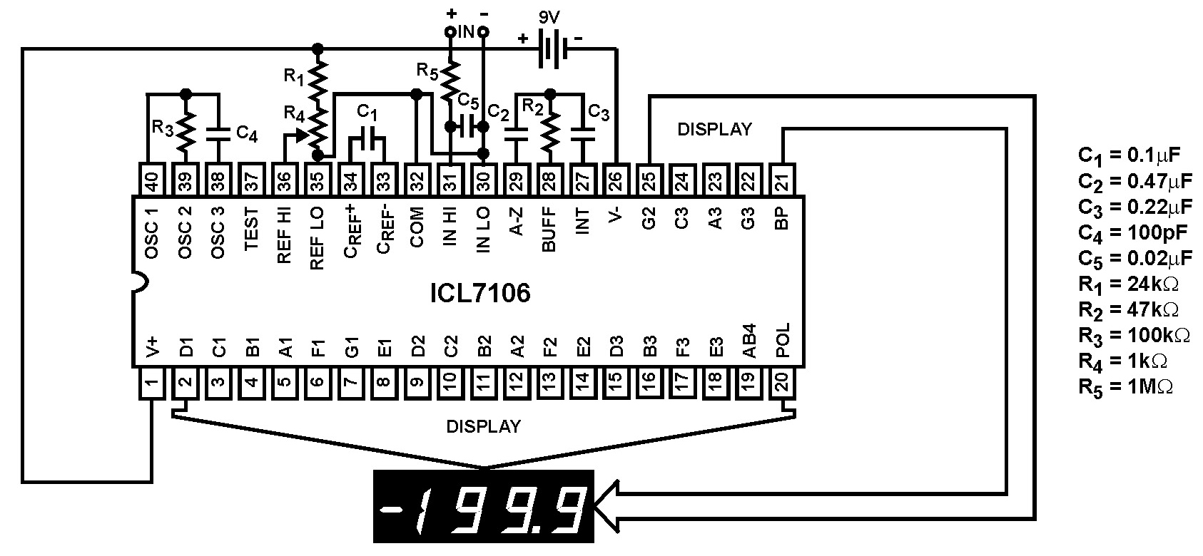
The Intersil ICL7106 and ICL7107 are high-performance, low-power, 3½ digit analog-to-digital (A/D) converters. They include seven-segment decoders, display drivers, a reference, and a clock. The ICL7106 is designed to interface with a liquid crystal display (LCD) and features a...
Control your instrument with a 4x20 LCD display and a 4x5 keypad designed for front panel feedback and control. The circuit involves an interface that utilizes a 4x20 LCD display and a 4x5 keypad, providing an effective means of user...

This is an automatic LCD panel backlight control circuit. It is a simple, low-cost implementation of an LED controller that can compensate for aging effects. The automatic LCD panel backlight control circuit is designed to enhance the performance and longevity...
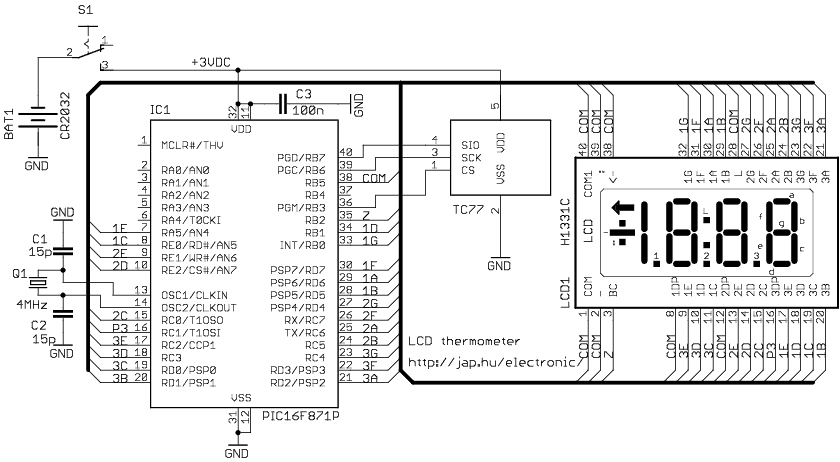
The circuit drives the LCD pins with 50% square waves. Each segment on this LCD is connected to the COM backplane and a separate pin. When a pin is driven in phase with the COM pin, the corresponding LCD...
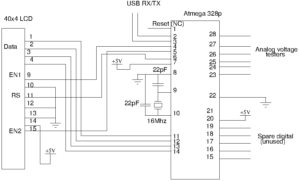
Drive a four-line LCD panel using an Arduino. The project initially aimed to control the LCD for displaying arbitrary information but evolved to include functionalities such as timekeeping, EEPROM read/write operations from the Atmel 328p, and voltage measurement. Multiple...