
Microcontroller driven LCD panel with voltage measurement time EEPROM for computers
EEPROM operations involve chunking the 1028 bytes of EEPROM into 8 segments of 128 bytes each, with Segment 0 designated as read-only, allowing for 128 bytes of ROM. To write to segment 3, the index command (:i3) is issued, followed by the write command (:wMySecretMessage). Reading from EEPROM requires the indexing first (:i3) and then executing the read command (:r). Voltage monitoring can be toggled at the analog pins (:a), with voltages displayed on the LCD in decivolts (e.g., 5.0V is represented as 50) and output in raw form on the serial interface (where 1023 equals 5V and 0 equals 0V). The complete Arduino source code is available as FourLinePanel.pde, which contains debugging information that prints each new command received; this debugging feature could be removed. Supported commands include: :t for displaying the time, :T<unix time> for setting the time, :l<message> for writing a message at the current position, :sN<message> for writing a message starting at segment N, :a for enabling analog voltage monitoring on the LCD and serial, :r for reading 128 bytes from EEPROM at the current location, :iN for indexing into segment N of the EEPROM, and :w<data> for writing data into EEPROM from the current location.
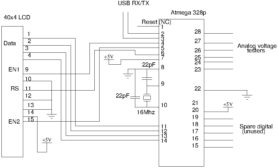
This project requires one Atmega microcontroller, an LCD panel, two 22pF ceramic capacitors, and one 16MHz crystal. A USB to serial cable may be needed for USB interfacing. The design powers the entire project through the USB port, minimizing the need for voltage regulation and additional components, as power over USB is typically clean. The schematic for the FourLinePanel can be downloaded. For computer interfacing, data is read from and written to the serial port at a baud rate of 38400 bits per second, with no flow control and no parity bits. An example program for interfacing with Python is provided, which sets the time on the FourLinePanel for GMT+5 hours.
Additionally, five spare digital pins are available for driving a Real Time Clock or LEDs, noted as "Spare Digital (unused)" in the circuit diagram. The analog voltage testers can serve as convenient tools for measuring voltage when a multimeter is not available or for continuously monitoring the voltage drop across devices such as photovoltaic cells.
This project exemplifies a versatile application of an Arduino in managing an LCD display, EEPROM data handling, and voltage monitoring, making it suitable for various informational and monitoring tasks in electronic projects.Drive a four line LCD panel from an Arduino. The project started out as a way to drive the LCD to display arbitrary information, but then evolved into a way to tell the time, read and write the EEPROM from the Atmel 328p, and measure voltage. I`m using many existing libraries: the Time library, and the two Controller LCD library. Segments the 40x4 display into 8 segments of 20 chars each. Segment 0 is column 0, line 0. Segment 1 is column 20 line 0. This allows an easy way to display up to eight different status updates. To write "hello world" in segment 3, you write ":s3helloworld " to the serial port. Read and write from EEPROM. The 1028 bytes of EEPROM is chunked into 8 segments of 128 bytes each. Segment 0 cannot be written to, which allows for 128 bytes of ROM. To write a segment 3, you index (:i3), then write (:wMySecretMessage ). To read from EEPROM, you index first (:i3), then read the full segment (:r). Voltage monitoring at analog pins can be toggled (:a). Voltages are displayed on the LCD (display shows all six pins in decivolts: 5. 0v is written 50) and written in raw form on serial (relative to 1023. 1023 = 5V, 0=0V) The entire Arduino source code is available as FourLinePanel. pde. It still has some debugging information left in, it prints the value of every new command it receives. This debugging could be removed. It supports a few commands: :t Displays the time :T
To interface it with USB, a USB to serial cable might be required. In my design, I`m driving the entire project using power from the USB port. This minimises the need for voltage regulation and additional components: power over USB is usually clean. You can download the schematic for the FourLinePanel here. To interface with a computer, you read and write to the serial port with 38400 bits per second, no flow control, and no parity bits.
An example program to interface this with Python is given below. import serial, time # Set the time on the FourLinePanel for GMT+5hrs # offset from GMT: Add 5hrs offset = 5*3600 port = "/dev/ttyUSB0" fourLine = serial. Serial(port, 38400); fourLine. write(":T" + str(int)(time. time() + offset) There are five spare digital pins that could be used to drive a Real Time Clock or LEDs.
These are marked as "Spare Digital (unused)" in the circuit diagram [png], and circuit diagram [ps]. The analog voltage testers can be used as handy ways to measure voltage at the desk when a multimeter isn`t handy, or to constantly monitor the voltage drop across a device (like a photovoltaic cell). 🔗 External reference
Related Circuits
Switching to alternative power sources can help reduce electricity bills. The photovoltaic module or solar panel described here is capable of generating renewable energy. The photovoltaic module, commonly known as a solar panel, is a device that converts sunlight into...
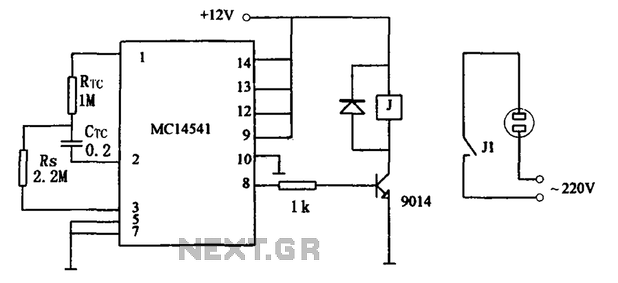
The circuit illustrated in FIG MC14541 is a straightforward timing circuit utilizing the MC14541 integrated circuit (IC). By adjusting the parameter map, the timing can be set for a duration of 3 hours, with options to select various RTC,...

The purpose of this application note is to present an example circuit illustrating the operation of the XR-T5683 device at a data rate of 10.1 Mbps. This note includes the results of measurements taken on the XR-T5683 at this...
Temperature indicators and temperature-based products have garnered significant interest due to their numerous applications and various possible solutions, each presenting unique advantages and disadvantages. This concept focuses on a sensor interface that delivers high accuracy while minimizing board space....
Project Manager Jim Heck, G3WGM, has provided an exclusive audio interview to Bob McCreadie, G0FGX, from TX Factor, detailing the tests and potential issues involved. Membership in AMSAT-UK is available to anyone interested in amateur radio satellites or space...
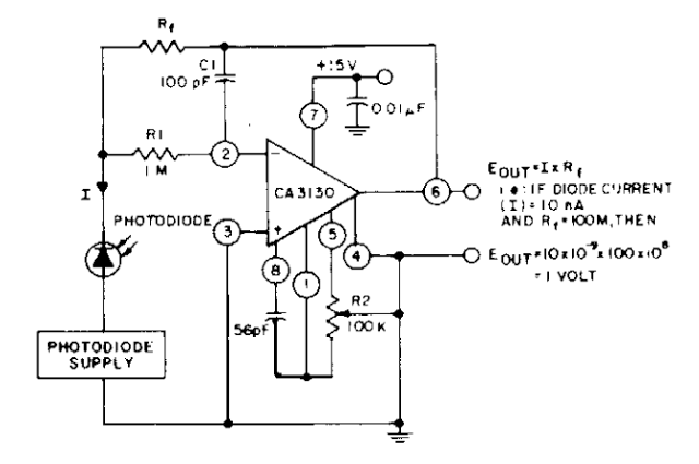
The photodiode current-to-voltage converter circuit employs three CA3130 BiMOS operational amplifiers, designed for applications that require sensitivity to sub-picoampere input currents. This circuit generates a ground-referenced output voltage that is directly proportional to the input current flowing through the...
Warning: include(partials/cookie-banner.php): Failed to open stream: Permission denied in /var/www/html/nextgr/view-circuit.php on line 713
Warning: include(): Failed opening 'partials/cookie-banner.php' for inclusion (include_path='.:/usr/share/php') in /var/www/html/nextgr/view-circuit.php on line 713