
Automatic Control for LCD Panel Backlight
The automatic LCD panel backlight control circuit is designed to enhance the performance and longevity of LCD displays by dynamically adjusting the backlight intensity based on various factors such as ambient light conditions and the aging of the LED backlight components. This circuit typically employs a feedback mechanism to monitor the brightness levels and adjust the LED current accordingly.
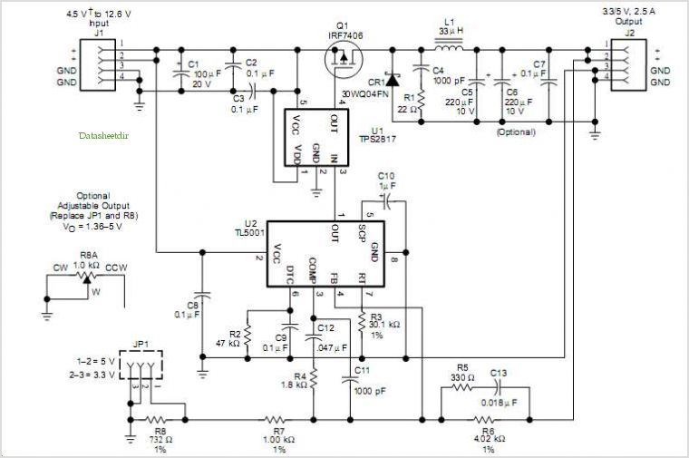
The fundamental components of this circuit include a light-dependent resistor (LDR) or photodiode for ambient light sensing, a microcontroller or operational amplifier for processing the input signals, and a pulse-width modulation (PWM) controller to regulate the LED backlight intensity. The LDR is connected to an analog input of the microcontroller, which interprets the light levels and determines the required backlight brightness.
To compensate for aging effects, the circuit may incorporate a calibration routine that periodically assesses the output brightness of the LEDs and adjusts the PWM duty cycle to maintain consistent illumination over time. This is crucial as LEDs tend to lose brightness with prolonged use, and this feature ensures that the display remains clear and readable throughout its lifespan.
Additionally, the circuit may include protection mechanisms to prevent over-driving the LEDs, such as current limiting resistors or feedback loops that monitor the LED temperature. The overall design aims to provide an efficient, cost-effective solution for managing LCD backlight systems, enhancing user experience while minimizing energy consumption.This is an Automatic LCD Panel Backlight Control circuit. This is a simple low cost implementation of an LED controller. It can compensate for aging effects.. 🔗 External reference
Related Circuits
The TVT-MOBI-2 will initially display a static image and will not respond to data from its serial interface, except for one function. The internal clock can be set by providing a date and time value, allowing it to calculate...
This small circuit is designed to verify the basic functionality of an infrared remote control unit. The circuit utilizes a straightforward approach by connecting a piezo buzzer directly to an IR receiver integrated circuit (IC). This configuration is as...
Most recent cars are equipped with a significant amount of electronics, including ABS brake systems, engine control with injection calculators, airbag activation, and various comfort functions. One such function, often overlooked due to its commonality, is the automatic activation...
The TLE6282G is an H-Bridge and Half Bridge Driver IC designed for high-current DC brush motor applications in PWM control mode. It is suitable for use in injector and valve applications across 12V, 24V, and 42V power networks. This...
This circuit controls a load (in this case a DC brushless fan) based on a temperature compared with a setpoint. The transducer is a diode in the forward polarization regime. In fact, when forward biased, the forward voltage drop...
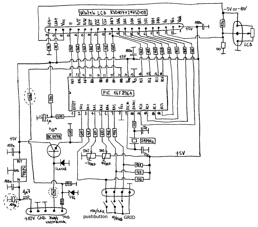
Spectrum-analyzer project 2007 update. Since the development of the wide-band VCO almost 10 years ago, the entire spectrum-analyzer project has progressed significantly. The spectrum analyzer project initiated in 2007 focuses on the development and enhancement of a wide-band Voltage Controlled...