
Lead Acid Battery Charger #2
This circuit operates as a constant current source with an integrated current limiting feature. The primary component, Q1, is a transistor that controls the output based on the current flowing through the circuit. Resistors R1 and R4 play critical roles in setting the current limit and ensuring stable operation. The calculated output voltage is contingent upon the values of P1, R2, and R3, which are essential for adjusting the output characteristics. For applications requiring fast charging, the circuit is designed to provide a specific voltage that corresponds to the battery configuration, ensuring compatibility with various battery types.
The use of a trimmer potentiometer (P1) allows for fine-tuning of the output voltage, providing flexibility in applications where precise voltage levels are necessary. The requirement for the input voltage to exceed the output voltage by at least 3 V is a crucial design consideration, as it ensures the LM317 regulator operates within its specified range, preventing dropout conditions that could lead to inefficiencies or operational failures.
Thermal management is paramount, especially for the LM317, which dissipates heat during operation. A large heat sink is recommended to maintain optimal operating temperatures and prevent thermal shutdown. The choice of Q1 is also significant; while the BC140 is a suitable option, alternatives such as the NTE128 or ECG128 can be employed without compromising performance, allowing for greater flexibility in component sourcing.
Overall, this circuit is versatile, functioning effectively as both a battery charger and a general-purpose power supply, making it suitable for a wide range of electronic applications. Its design emphasizes reliability, efficiency, and adaptability, catering to various voltage and current requirements.The above pictured schematic diagram is just a standard constant current model with a added current limiter, consisting of Q1, R1, and R4. The moment too much current is flowing biases Q1 and drops the output voltage. The output voltage is: 1. 2 x (P1+R2+R3)/R3 volt. Current limiting kicks in when the current is about 0. 6/R1 amp. For a 6-volt batte ry which requires fast-charging, the charge voltage is 3 x 2. 45 = 7. 35 V. (3 cells at 2. 45v per cell). So the total value for R2 + P1 is then about 585 ohm. For a 12 V battery the value for R2 + P1 is then about 1290 ohm. For this power supply to work efficiently, the input voltage has to be a minimum of 3V higher than the output voltage. P1 is a standard trimmer potentiometer of sufficient watt for your application. The LM317 must be cooled on a sufficient (large) coolrib. Q1 (BC140) can be replaced with a NTE128 or the older ECG128 (same company). Except as a charger, this circuit can also be used as a regular power supply. 🔗 External reference
Related Circuits
The circuit described is suitable for indicating the capacity of a battery using a low-cost electric clock. By connecting a resistor across the battery terminals, the battery discharges at a faster rate than it would with the clock alone....
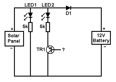
A small solar panel is used to maintain a 12V car battery. The panel provides approximately 75mA of current to the battery under full sunlight conditions. The described circuit employs a solar panel specifically designed for battery maintenance applications. The...
A car battery deteriorates in use, and its life seldom exceeds four years. When new, its voltage may drop to only 2V while cranking the engine. A car battery, typically a lead-acid type, is essential for providing the necessary electrical...
A short-circuit-proof battery charger provides an average charging current of approximately 8 A to a 12-V lead/acid storage battery. The charger circuit has the additional advantage of being unaffected and undamaged by incorrect battery connections. With an input voltage...
This circuit performs a rapid battery test without requiring a power supply or costly moving-coil voltmeters. It offers two testing ranges: when switch SW1 is positioned as indicated in the circuit diagram, the device can test batteries ranging from...
Schematic and description of a simple and easy-to-build NiCd and NiMH battery charger circuit that is capable of charging multiple NiCd and NiMH batteries. The circuit for the NiCd and NiMH battery charger is designed to be straightforward, allowing for...