
nicd nimh battery charger circuit
The circuit for the NiCd and NiMH battery charger is designed to be straightforward, allowing for the charging of multiple batteries simultaneously. The schematic typically includes a power supply, a charging control circuit, and battery connections.
The power supply can be a standard AC to DC adapter that provides the necessary voltage and current for charging. The charging control circuit often consists of a voltage regulator, which ensures that the output voltage remains stable and appropriate for charging NiCd and NiMH batteries.
A common configuration may include a series of resistors and diodes to manage the charging current and protect against reverse polarity. Additionally, a microcontroller or simple comparator circuit can be integrated to monitor the battery voltage and terminate charging once the batteries reach full charge, preventing overcharging and extending battery life.
Battery connections are typically made using a terminal block or soldered connections, allowing for easy attachment and detachment of the batteries. It is essential to ensure that the circuit is designed to handle the specific voltage and current ratings of the batteries being charged, with appropriate safety features such as fuses or thermal cutoffs to prevent overheating.
In summary, this charger circuit is a practical solution for charging multiple NiCd and NiMH batteries, combining simplicity in design with effective charging capabilities. Proper attention to component selection and circuit layout is crucial for optimal performance and safety.Schematic and description of a simple and easy to built NiCd and Nimh battery charger circuit which is able to charge multiple NiCd and NiMH batteries. .. 🔗 External reference
Related Circuits
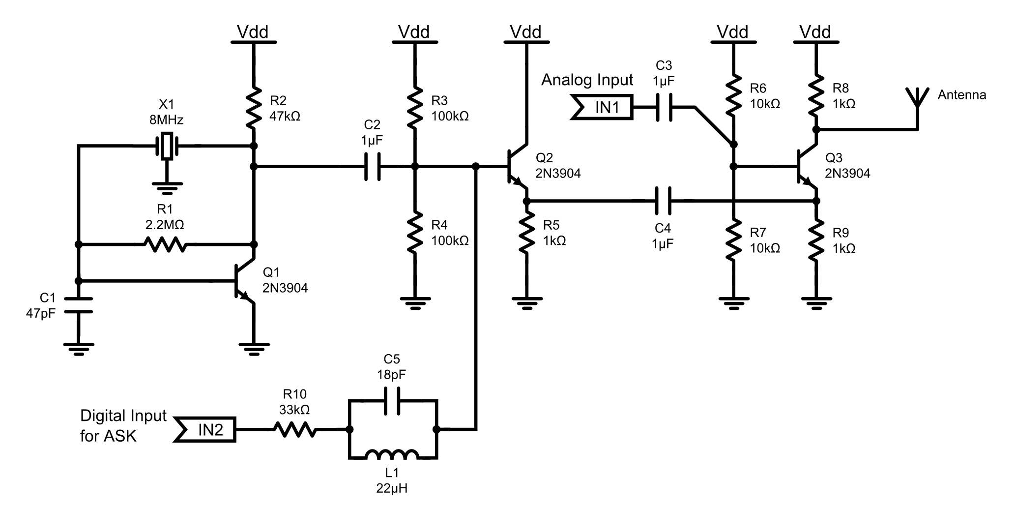
This is an 8MHz amplitude modulated (AM) radio transmitter designed primarily for practical applications and as an educational exercise in electronics. The objective was to create a simple radio transceiver that could be used in future projects requiring basic...
The circuit for the ball game scoring device is depicted in the accompanying image. This device records and displays the performance of a ball game. The first Nixie tube has two states: it can either be off or display...
A battery-operated Tesla coil is being developed, and assistance is needed for converting direct current (DC) to alternating current (AC) to power a high-voltage transformer. To convert DC to AC for powering a high-voltage transformer in a Tesla coil circuit,...
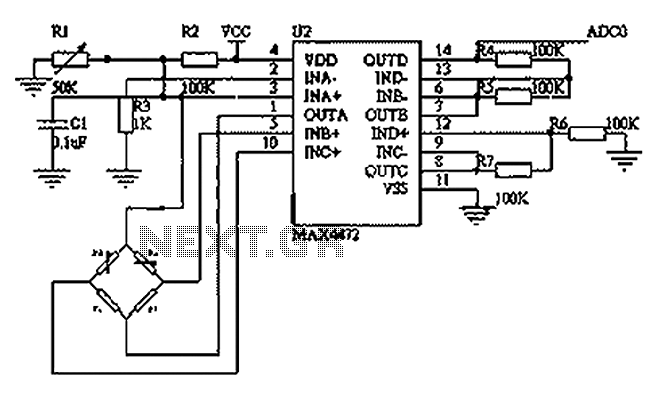
This circuit utilizes a BP01-type pressure sensor and the MAX4472 operational amplifier. The BP01 pressure sensor is specifically designed for blood pressure detection and is primarily used in portable electronic sphygmomanometers. It features a precision thick film ceramic chip...
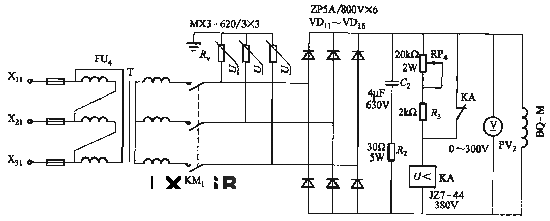
FIG T is the excitation transformer, R is a varistor, and there are rectifier diodes to protect against breakdowns from VDii to VD16; Rz and C2 provide resistive-capacitive protection. The circuit is designed to absorb voltage from the magnetic...
The bi-directional sequencer utilizes a 4-bit binary up/down counter (CD4516) and two "1 of 8 line decoders" (74HC138 or 74HCT138) to create the well-known "Night Rider" display. A Schmitt Trigger oscillator generates the clock signal for the counter, with...