
Self-Powered Fast Battery Tester Schematic
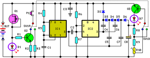
LED D1 and the base of Q2 are configured such that D1 illuminates at a consistent intensity, regardless of the battery voltage within the 3V to 15V range. When switch P1 is closed, Q2 applies a constant current load of approximately 120mA to the battery. The integrated circuit IC1 operates as a square wave generator oscillating at around 3kHz. IC2 serves as an inverter, driving diodes D2-D6 and capacitors C4-C7 in an anti-phase manner to achieve voltage multiplication. Capacitor C8 is charged by this elevated voltage, while resistors R8-R10 form a voltage divider that biases the base of transistor Q3.
When P1 is open, a minimal load is applied to the battery under test, keeping LED D7 in the off state due to the biasing of Q3's base. Upon closing P1, a 120mA load is imposed on the battery. If the battery is not fully charged, its output voltage begins to decrease. When this voltage drops 0.6V below the nominal voltage, the emitter of Q3 becomes more negative than its base, causing the transistor to become hard biased, which results in LED D7 illuminating. This condition persists for a few seconds, determined by the time required for C8 to discharge to the new voltage level, which is proportional to the loaded battery's voltage. If the battery is adequately charged, its output voltage remains above the threshold under a 120mA load, and LED D7 remains off. For testing 1.5V batteries, the circuit comprising Q1, Q2, D1, and resistors R1 and R2 is ineffective at this lower voltage, so a 150mA load current is applied to the battery under test through a 10-ohm resistor R3 after switching SW1A. The biasing of Q3 is also adjusted via switch SW1B.
The circuit is designed to provide an efficient and cost-effective means of testing battery performance across different voltage ranges. The use of FETs and integrated circuits ensures that the circuit operates with high precision and reliability. The dual range capability enhances its versatility, allowing it to accommodate various battery types with minimal adjustments. The incorporation of LED indicators provides immediate visual feedback on battery status, making it user-friendly. This testing circuit can be particularly useful in applications where quick battery assessments are required, such as in consumer electronics or maintenance settings.This circuit runs a fast battery test without the need of power supply or expensive moving-coil voltmeters. It features two ranges: when SW1 is set as shown in the circuit diagram, the device can test 3V to 15V batteries.
When SW1 is switched to the other position, only 1. 5V cells can be tested. FET Q1 provides a constant current generator biasing LED D1 and Q2 Base. In this manner D1 illuminates at a constant intensity, independent of battery voltage from 3 to 15V and Q2 (when P1 is closed) applies a constant current load of about 120mA to the battery. IC1 is a square wave generator oscillating at about 3KHz. IC2 acts as an inverter and drives, together with IC1 but in anti-phase, Diodes D2-D6 and Capacitors C4-C7, obtaining a voltage multiplication.
C8 is charged by this raised voltage and R8-R10 form a voltage divider biasing the Base of Q3. When P1 is open, a very light load is applied to the battery under test and Q3 Base is biased in order to maintain LED D7 in the off state. Closing P1, a 120mA load is applied to the battery under test. If the battery is not fully charged, its output voltage starts reducing: when this voltage fall 0. 6V below the battery nominal voltage, Q3 Emitter becomes more negative than the Base, the transistor is hard biased and D7 illuminates.
Obviously, this state of affairs will last a few seconds: the time spent by C8 to reduce its initial voltage to the new one, proportional to the voltage of the loaded battery. If the battery under test is in a good charging state, its output voltage will not fall under a 120mA loading current, so LED D7 will stay off.
When testing 1. 5V batteries, the circuit formed by Q1, Q2, D1, and R1 & R2 does not work well at this supply voltage, so a 150mA load current is applied to the BUT by means of the 10 Ohm resistor R3 after switching SW1A. Q3 bias is also changed via SW1B. 🔗 External reference
Related Circuits

This circuit utilizes a pair of Zener diodes to monitor the voltage of a 12-V battery. When the voltage drops below 11 V, diode D1 ceases to conduct, causing pin 3 of flip-flop IC2 to go high. This action...
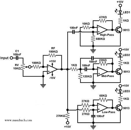
A simple circuit for converting an audio signal (such as one that comes from the output terminals of a CD player). The circuit basically consists of a buffer/amplifier stage and three filter circuits: a high-pass filter, a mid-pass filter,...
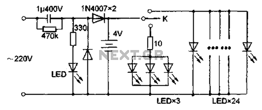
The circuit diagram depicted in Figure 5 illustrates a system for charging a lead-acid battery using 220V AC power. The circuit employs a capacitor, buck converter, and diode rectifier for this purpose. A red LED indicates the charging status....
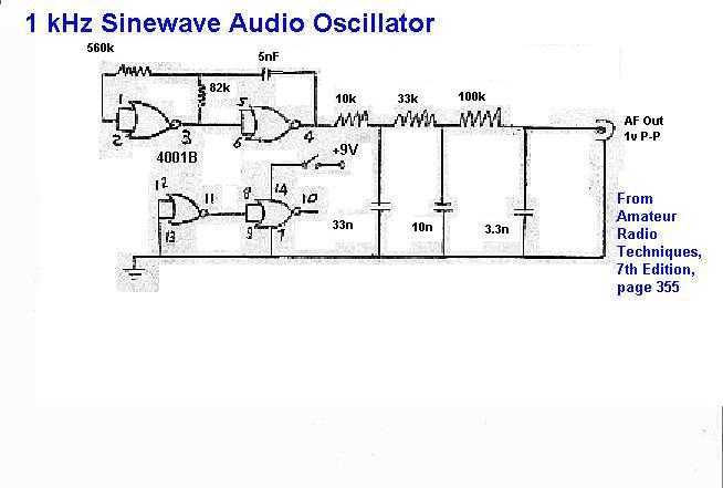
This circuit consists of a CMOS square wave oscillator on a frequency of approximately 1 kHz. The RC filter, which has a roll-off frequency of 500 Hz, filters the harmonics, providing a sine-wave output. The described circuit features a...

This circuit was created for digital cameras. It's known the digital cameras have considerable power consumption. For example, my camera Minolta E223 requires approximately 800 mA. In practice, a mains power supply or high capacity NiMH accumulators (batteries) can...
Nokia BL-4C and BL-5C are 3.7V, 700-1000mAh (various) lithium-ion batteries that have three terminals. These terminals include a positive terminal, a ground, and a BSI (Battery Status Indicator) terminal, which presents a fixed resistance value that needs to be...