
Lead-Acid Battery Charger

The Lead-Acid battery charger circuit is designed to efficiently manage the charging process of lead-acid batteries while ensuring their longevity. The initial charging voltage of 2.5 V per cell allows for a fast charging phase, which is critical for applications requiring quick turnaround times. The transition to a lower float voltage of 2.35 V per cell is vital for maintaining the battery's health, as it prevents excessive charging that could lead to battery damage.
The LM301A comparator plays a crucial role in the circuit by monitoring the voltage across R1, which is directly influenced by the charging current. By comparing this voltage to the fixed reference voltage of 18 mV provided by R2, the LM301A can accurately determine when to switch the output voltage to the float level. This feedback mechanism is essential for automatic regulation of the charging process, ensuring that the battery is charged to optimal levels without the risk of overcharging.
The inclusion of temperature compensation through the LM334 sensor is particularly important as battery performance can be significantly affected by temperature variations. By adjusting the charging voltage based on temperature, the circuit can maintain optimal charging conditions, which is especially beneficial in environments where temperature varies widely.
The design also allows for flexibility in current handling, with the option to select different voltage regulators based on the application's current requirements. This scalability ensures that the charger can be adapted for various battery sizes and types, making it a versatile solution for lead-acid battery management.
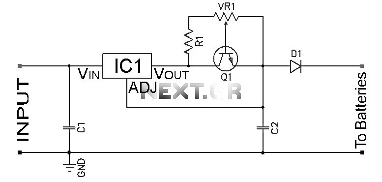
Overall, this Lead-Acid battery charger circuit is a well-engineered solution that balances efficiency, safety, and adaptability, making it suitable for a wide range of applications involving lead-acid batteries.The following diagram is the circuit diagram of Lead-Acid battery charger. This circuit provides an initial voltage of 2. 5 V per cell at 25 ƒ to quickly charge the battery. The charging current decreases as the battery is charging, and wh This circuit provides an initial voltage of 2. 5 V per cell at 25 ƒ to quickly charge the battery. The charging current decreases as the battery is charging, and when the current drops to 180 mA, the charging circuit reduces the output voltage of 2. 35 V per cell, leaving the battery in a fully charged state. This lower voltage prevents the battery from overcharging, which would shorten its life. The LM301A compares the voltage drop across R1 with an 18 mV reference set by R2. The comparator`s output controls the voltage regulator, forcing it to produce the lower float voltage when the battery-charging current, passing through R1, drops below 180 mA.
The 150 mV difference between the charge and float voltages is set by the ratio of R3 to R4. The LEDs show the state of the circuit. Temperature compensation helps prevent overcharging, particularly when a battery undergoes wide temperature changes while being charged. The LM334 temperature sensor should be placed near or on the battery to decrease the charging voltage by 4 mV/ƒ for each cell.
Because batteries need more temperature compensation at lower temperatures, change R5 to 30 ©for a tc of -5 mV/ƒ per cell if application will see temperatures below -20ƒ. The charger`s input voltage must be filtered dc that is at least 3 V higher than the maximum required output voltage: approximately 2.
5 V per cell. Choose a regulator for the maximum current needed: LM371 for 2 A, LM350 for 4 A, or LM338 for 8 A. At 25ƒ and with no output load, adjust R7 for a VOUT of 7. 05 V, and adjust R8 for a VOUT of 14. 1V. 🔗 External reference
Related Circuits
Many battery-powered devices use two AA alkaline cells. Often, it is not apparent when it is time to replace the batteries until the device powered by them ceases to function. In battery-powered devices that utilize two AA alkaline cells, it...
Adjustable Constant Current Ni-Cd and Ni-MH Battery Charger Circuit. This circuit is designed to provide a constant current for charging Ni-MH or Ni-Cd batteries. A schematic diagram of the circuit is available. The adjustable constant current battery charger circuit for...
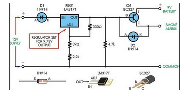
Although smoke alarms are relatively inexpensive devices, the cost of 9V batteries can quickly surpass their initial purchase price. Additionally, the annoyance of random beeping can be a significant drawback. Smoke alarms are essential safety devices designed to detect smoke...
A car battery deteriorates in use, and its life seldom exceeds four years. When new, its voltage may drop to only 2V while cranking the engine. A car battery, typically a lead-acid type, is essential for providing the necessary electrical...
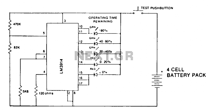
A state-of-charge indication of a sloping-voltage discharge can be utilized as a state-of-charge indicator. A typical voltage comparator circuit that provides a visual indication of the state of charge is presented. Components identified are for a 4-cell input voltage...
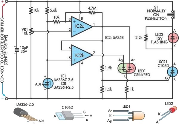
Camping today often requires bringing various electronic devices for daily activities or entertainment. Frequently, a charge is needed for these devices. In modern camping scenarios, the reliance on electronic devices has significantly increased. Campers typically bring smartphones, tablets, GPS devices,...