
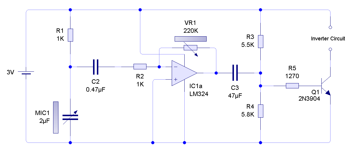
Circuit Project: 3V Low Battery Voltage Flasher
In battery-powered devices that utilize two AA alkaline cells, it is critical to monitor the battery life to ensure consistent operation. These devices typically operate within a voltage range of 2.4V to 3.0V when fully charged, which is sufficient for most low-power applications. The performance of the device may degrade as the battery voltage drops below the operational threshold, leading to unexpected shutdowns or malfunctions.
To address the issue of battery life monitoring, a simple battery level indicator circuit can be integrated into the design. This circuit may consist of a voltage divider connected to an analog-to-digital converter (ADC) that interfaces with a microcontroller. The microcontroller can periodically sample the battery voltage and compare it against predefined thresholds to determine the state of the battery. If the voltage falls below a certain level, the microcontroller can activate an LED indicator or send a notification to the user, prompting them to replace the batteries.
Additionally, implementing a low-power microcontroller can enhance energy efficiency, extending the overall battery life of the device. Incorporating sleep modes and optimizing the circuit design to minimize current consumption during idle states can also contribute to prolonged battery operation.
In summary, while devices powered by two AA alkaline cells are common, integrating a battery monitoring solution can significantly improve user experience by providing timely notifications for battery replacement, thereby preventing unexpected device failures.Many battery powered devices use two AA alkaline cells. Often you will not know when it is time to replace the batteries until the device powered by them.. 🔗 External reference
Related Circuits
This simple circuit can be utilized to activate various devices, such as microcontrollers, relays, secret alarms, or robot applications. It can also be used to turn on LED1, which remains illuminated as long as the metal plate is touched....

The transmitter utilizes a 6BW6 vacuum tube to achieve an output power of approximately 5 watts. The circuit includes a component CI that is calibrated to produce the cleanest continuous wave (CW) note. The tuning capacitors C8 and C9...

The bridge shown was used for measurements on 50-MHz amateur radio antennas. Rl is a miniature 500 linear potentiometer. The unknown impedance is compared to R2, a 51-ohm resistor. An external signal source is required. The described bridge circuit is...
A ready-made inverter circuit was utilized to drive the EL sheet; therefore, the diagram is incomplete. Additionally, the battery consumption appears to be significantly higher than expected. An AVI video file without sound, recorded using a webcam, is available...

The circuit illustrated in Figure 3-56 features both manual and automatic start-up modes. It incorporates two relays, KA2 and KA3, within the control loop. The circuit design ensures that KM1 is cut off before and after activating KM2. A...
The circuit was designed to create an alarm system that alerts a sleeping person to prevent snoring by utilizing a vibrator instead of an audio alert. The circuit operates on the principle of detecting snoring sounds through a microphone or...
Warning: include(partials/cookie-banner.php): Failed to open stream: Permission denied in /var/www/html/nextgr/view-circuit.php on line 713
Warning: include(): Failed opening 'partials/cookie-banner.php' for inclusion (include_path='.:/usr/share/php') in /var/www/html/nextgr/view-circuit.php on line 713