
Lead Acid Battery Charger Circuit
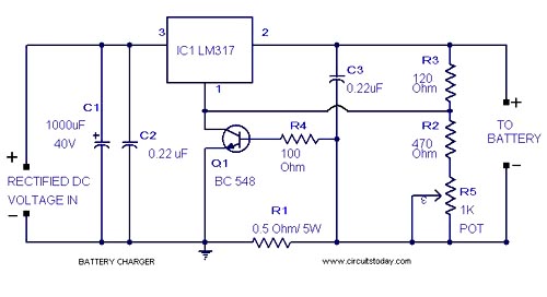
The lead-acid battery charger circuit utilizes the LM317 voltage regulator IC, which is known for its adjustable output voltage capabilities. The circuit is designed to provide a stable charging voltage suitable for lead-acid batteries, typically in the range of 13.8 to 14.4 volts, depending on the specific battery type and charging requirements.
The circuit configuration consists of the LM317 IC, several resistors, and capacitors to stabilize the output voltage and improve performance. The input voltage of 18 volts is supplied to the LM317, which regulates this voltage down to the desired charging voltage. The output voltage is adjustable by using two resistors (R1 and R2) connected to the adjustment pin of the LM317. The values of these resistors can be chosen based on the formula provided in the LM317 datasheet, which allows for precise control of the output voltage.
Additionally, it is advisable to include input and output capacitors (typically 0.1µF and 10µF) to filter any noise and ensure stable operation. A heat sink may be necessary for the LM317, as it can generate heat during operation, especially when there is a significant difference between the input and output voltages.
This charger circuit is suitable for charging small to medium-sized lead-acid batteries and can be used in various applications, including automotive and backup power systems. Proper safety measures should be observed when working with lead-acid batteries, as they can emit gases and require proper ventilation during charging.A simple lead acid battery charger circuit with diagram and schematic using IC LM 317,which provides correct battery charging voltage. This lead acid battery charger should be given an input 18 Volts to IC.. 🔗 External reference
Related Circuits
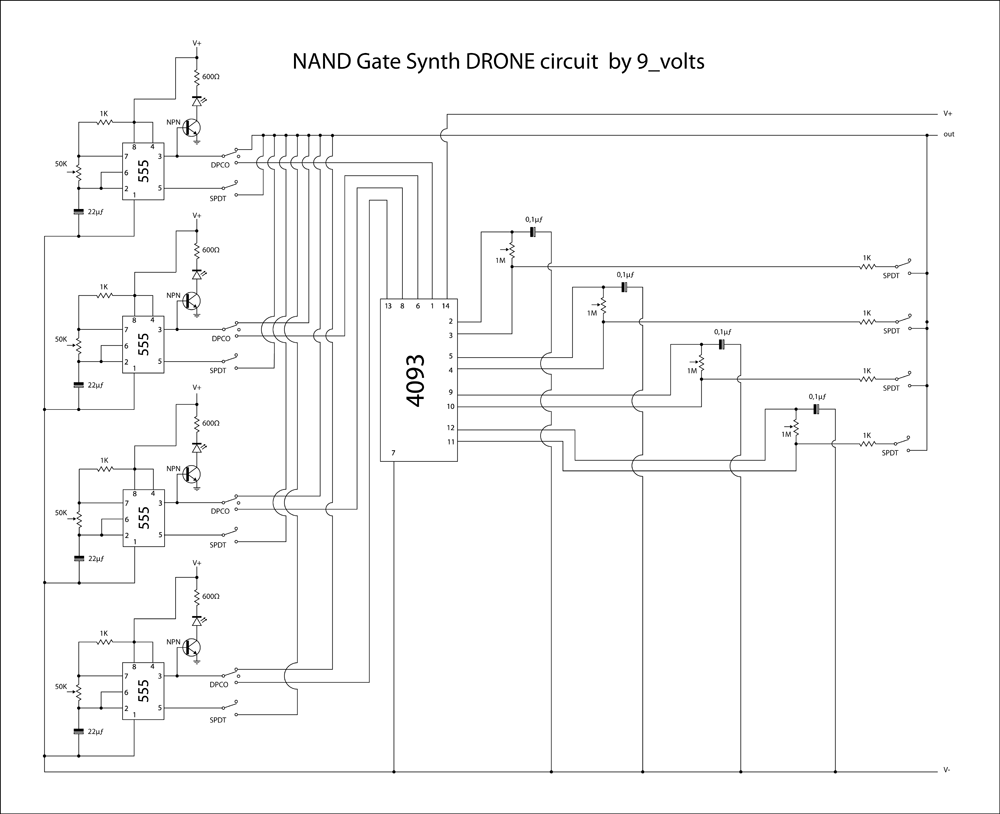
This is a brief jam session to explore the capabilities of a recently completed step sequencer. This device is quite enjoyable and expands creative possibilities. A detailed post with the circuit and instructions for building it will be provided...
This TDA2030 35-watt audio amplifier circuit project is designed to deliver an output power of 35 watts into an 8-ohm load. The TDA2030 is a monolithic integrated circuit housed in a Pentawatt package, intended for use as a low-frequency...
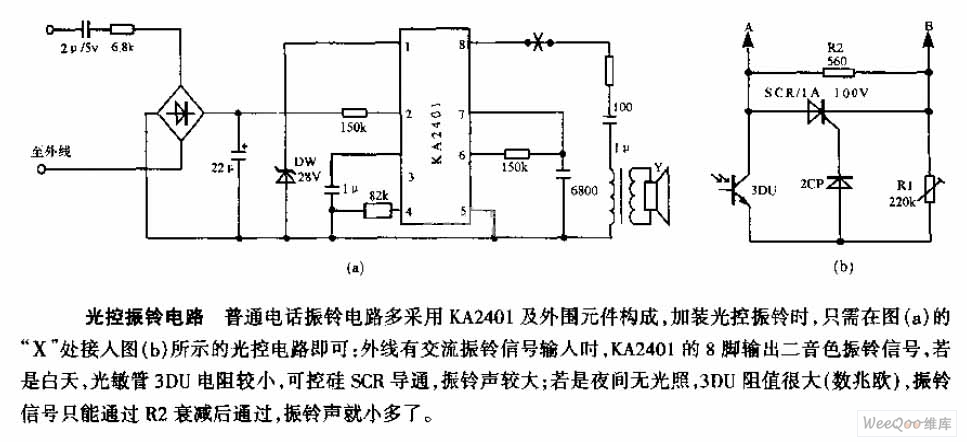
The average telephone ring circuit consists of the KA2401 integrated circuit and its associated peripheral components. To integrate a light-operated ring circuit, connect the designated part X in the provided diagram (picture a) to the light-operated circuit shown in...
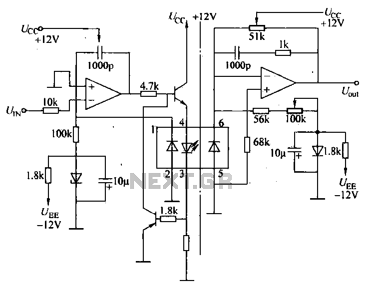
A universal optocoupler is utilized in electrocardiographs, as illustrated in Figure 5-29. Pin connections must be made carefully: the positive terminal should be connected to pin O, while the negative terminal should connect to the other pin. The control...
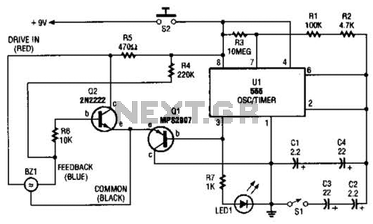
The electronic darkroom timer is constructed using a 555 oscillator/timer, a pair of general-purpose transistors, a buzzer, and an LED. The 555 timer (U1) is set up as an astable multivibrator, functioning as a free-running oscillator. The frequency of...

A subsonic filter is primarily utilized in low-frequency technology. It is commonly employed to eliminate very low frequencies that can cause distortions in music recording or reproduction. A subsonic filter is an electronic circuit designed to attenuate frequencies below a...
Warning: include(partials/cookie-banner.php): Failed to open stream: Permission denied in /var/www/html/nextgr/view-circuit.php on line 713
Warning: include(): Failed opening 'partials/cookie-banner.php' for inclusion (include_path='.:/usr/share/php') in /var/www/html/nextgr/view-circuit.php on line 713