
Optical coupling electrocardiogram measuring instrument circuit

A universal optocoupler serves as a crucial component in electrocardiography, enabling the isolation of electrical signals while maintaining signal integrity. The circuit design, as depicted in Figure 5-29, emphasizes the importance of correct pin connections to ensure proper functionality. Specifically, pin O must be connected to the positive voltage supply, while the corresponding negative terminal connects to the ground. This proper biasing is essential for the optimal performance of the optocoupler.
The control circuit, indicated by the dashed line on the left side of the figure, plays a vital role in signal processing. It facilitates the input of the signal to the arc tube connected to pin O. The photodiode, which is integral to the optocoupler's operation, receives light from pin O and generates an output signal. This output is then combined with an additional input from UIr.a, which is directed into an operational amplifier. The operational amplifier amplifies the combined signal, and the feedback mechanism is critical for maintaining the linearity of the optocoupler's response. This feedback not only enhances performance but also reduces signal drift, which is essential for accurate readings in electrocardiographic applications.
On the right side of the dashed line, the main loop circuit processes the light signals emitted from pins O and @. The operational amplifier's output is amplified, providing a robust signal that controls the subsequent stages of the circuit. This amplification is vital for ensuring that the signals are strong enough to be processed further, allowing for accurate representation of the heart's electrical activity.
The successful integration of linear optocoupler tuners in electrocardiographs demonstrates their effectiveness in medical instrumentation. Their application is expanding beyond electrocardiography to include converters and various other devices, showcasing their versatility and reliability in electronic circuit design.Tuner universal optocoupler should be on the electrocardiograph use, it is a typical circuit is shown in Figure 5-29. Circle O, feet should be connected to the positive; , feet to negative, make no mistake. From Figure 5-29 to see stern dotted line on the left is a control circuit, the signal input to , foot arc tube; O, feet after a light receiving photodiode output signal together with UIr.a input into an operational amplifier, the feedback signal to a linear optocoupler linearity and reduce drift are helpful. The right of the dotted line is the main loop circuit, LED light signals emitted by O, , @, feet to receive.
, feet clamor operational amplifier output signal. Amplified output, which controls the post-stage circuit. Linear optocoupler tuner has been in electrocardiograph in successful applications, and also the converter and other instruments in the gradual application.
Related Circuits

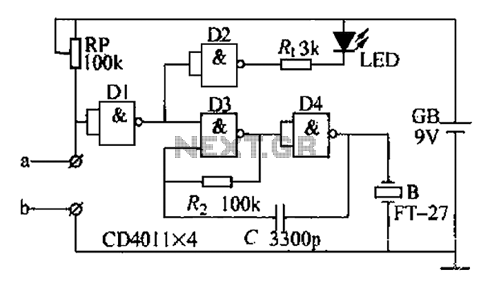
This circuit is designed for sound detection and generates an output signal when sound is detected. This output can trigger another circuit that activates an alarm, making it suitable for security applications. The circuit employs a condenser microphone to...
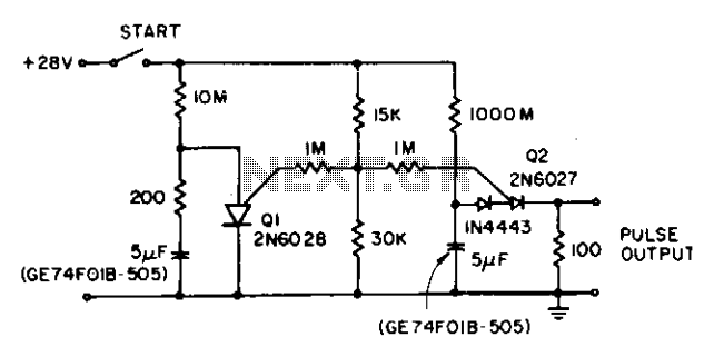
The circuit reduces the effective peak current of the output PUT, Q2. It allows the capacitor to charge with a high gate voltage and periodically lowers the gate voltage. When Q1 fires, the timing resistor can be set to...
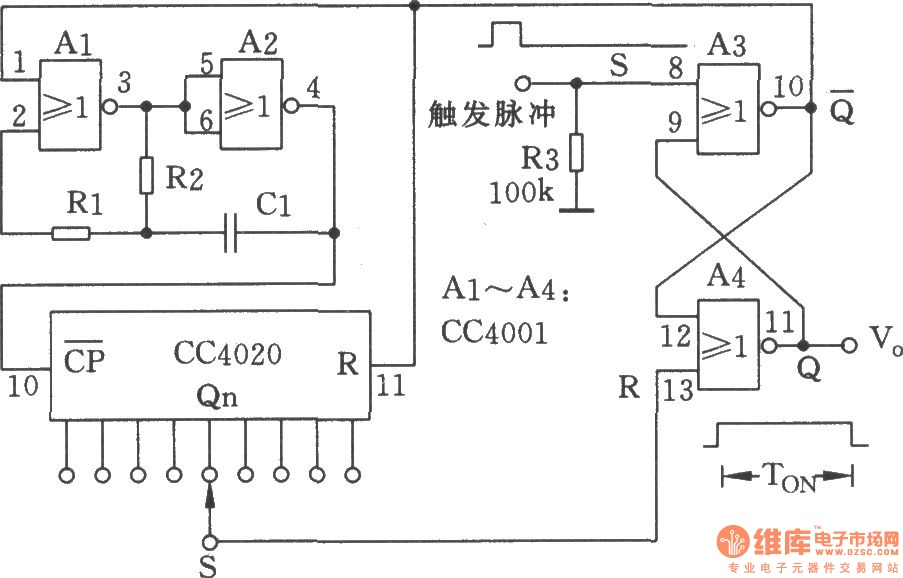
The NC monostable multivibrator circuit depicted in the chart consists of four 2-input NOR gates (CC4001) and a 14-bit binary serial counter/divider (CC4020). It is primarily utilized as a time delay switch or timer in automatic control equipment. The NC...
An annual listing of the watermelon season reveals that many individuals lack the intuitive judgment to differentiate between raw and cooked watermelon. This often leads to unnecessary disputes regarding the classification of the fruit. A proposed solution is the...
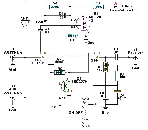
A simple and efficient active antenna electronic project can be designed using this electronic schematic circuit based on transistors. This active antenna project is effective for a wide range of RF frequencies, covering three RF bands: HF, VHF, and...
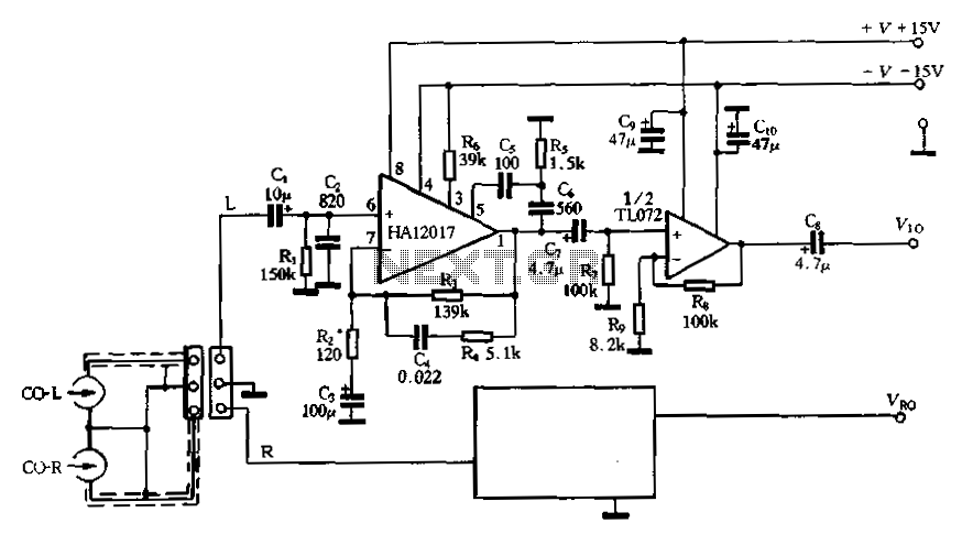
Figure 3-16 illustrates a low-noise preamplifier equalizing circuit using the HA12017. This circuit includes playback components R3, R4, and C4, which conform to a standard balanced network. The gain of the circuit is -7dB at 1kHz, while the output...