
learning How does this SIM card reader circuit work
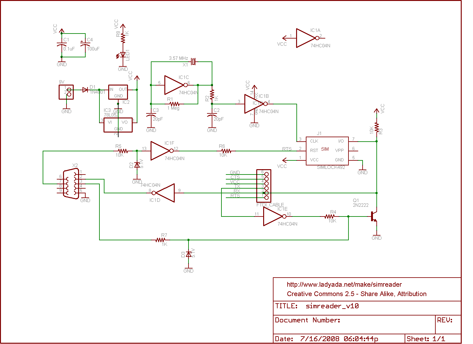
The SIM card reader circuit is designed to interface with SIM cards and enable communication with a PC. The core component of this circuit is the CMOS hex inverter, which is used to convert the logic levels of the signals from the SIM card to levels that can be understood by the PC. The circuit may include additional passive components such as resistors and capacitors to stabilize the signal and filter noise, ensuring reliable communication.
The circuit can be powered by a standard power supply, which should be compatible with the voltage requirements of the CMOS components. The connection to the PC is typically made through a DB9 serial port, which allows for straightforward data transmission. However, it is crucial to note that the voltage levels outputted through the DB9 connector are TTL levels, which are not suitable for direct RS232 communication. To achieve RS232 compatibility, a level shifter or RS232 driver may be required to convert the TTL signal levels to the appropriate voltages.
When designing or assembling this circuit, careful attention should be paid to the layout and connections to prevent any signal integrity issues. Proper grounding and decoupling techniques should be employed to minimize interference and ensure stable operation. As this circuit is aimed at hobbyists and beginners, clear documentation and schematic diagrams should accompany the design to facilitate understanding and implementation.
Overall, this SIM card reader circuit serves as an excellent introduction to electronic design and interfacing, providing valuable hands-on experience in working with digital signals and communication protocols.The circuit for a SIM card reader is shown here. The circuit uses a CMOS hex inverter and other simple components; yet, not only does it work but it can also communicate with a PC via serial port! I am learning electronic circuits as a hobby and I was baffled to see how simple this was. I was thinking of using some kind of micro controller for th is. As you can see I am a complete amateur. Olin wanted you to learn by doing - and it is often the best way to learn. I wanted to use the link as intened so fixed it BUT you should always check your links after positing to make sure they are OK. The problem was small but fatal. Links are of form [label stuff](URL) with no gaps between ] and (. You had a space between ] and ( so it didn`t work. Russell McMahon Dec 29 `11 at 13:55 Please note that the signal levels going out on the DB9 header are not RS232 compliant.
RS232 should be (I believe) +/- 9V atleast, and this only does 0. 5V (known as TTL) Hans Dec 29 `11 at 20:48 🔗 External reference
Related Circuits

A very simple dimmer circuit with only the essentials. In this circuit, the values are given for a BT138 at 220V AC. For 115V AC, experimentation with values may be necessary. R1 can vary from one triac to another;...

This is a sensor circuit designed for light detection. It utilizes the LM311 comparator and features a simple design. The comparator is powered by a 12 V DC supply and does not require a negative supply for efficient operation....
The LM358 consists of two independent, high-gain operational amplifiers in a single package. An important feature of this integrated circuit (IC) is that it does not require separate power supplies for the operation of each comparator, accommodating a wide...
This simple and inexpensive crystal oscillator consists of one-third of a 7404 hex inverter, four resistors, and a crystal. The inverters are biased into their linear regions by resistors R1 to R4, while the crystal provides the necessary feedback....
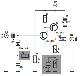
The video amplifier in the diagram represents a well-established design that is both simple and highly functional. However, it is important to note that the transistors can be easily damaged if the potentiometers (black level and signal amplitude) are...
With this circuit mounted in or near every phone in the house, it will allow users to know if the phone is being used and not to pick up the phone. When a phone is taken off hook, the...