
simple lamp dimmer 220v using triac

The described dimmer circuit utilizes a BT138 triac, which is designed to control the power delivered to a load, such as a lamp, by varying the phase angle of the AC waveform. This circuit is particularly simple, containing only the essential components required for dimming functionality.
The circuit operates by using a resistive element (R1), which is crucial for triggering the triac. The value of R1 may differ between various triac models, necessitating the use of a variable resistor, specifically a 220K ohm trimmer, during the initial setup phase. This trimmer allows for fine-tuning of the circuit to achieve the desired dimming effect. Once the optimal setting is determined through measurement, the trimmer should be replaced with a fixed resistor of the same value to maintain stability and reliability in operation.
The dimmer circuit is designed to function at 220V AC, but adjustments may be required for operation at 115V AC. This may involve changing the values of other components in the circuit to ensure proper functionality and safety at lower voltages. It is crucial to ensure that all components are rated for the voltage and current levels present in the application to avoid potential hazards.
In summary, this simple dimmer circuit exemplifies a basic yet effective method of controlling the brightness of incandescent lamps using a triac. Proper component selection and adjustments are key to achieving optimal performance in various voltage applications.A very simple dimmer circuit with only the essentials. (In this circuit, the values are given for a BT138 at 220V AC, for 115V AC you may have to experiment with the values. ) R1 can vary from one triac to another, put a 220K © trimmer in its place and adjust. After adjustment, measure the result and replace the trimmer with an ordinary resistor of the same value. 🔗 External reference
Related Circuits
This circuit utilizes the widely available LM3914 integrated circuit (IC). The LM3914 is straightforward to operate, does not require external voltage regulators due to its built-in voltage regulation, and can be powered from nearly any voltage source. This makes...
This page is provided to the domain owner free by Sedo's Domain Parking. Disclaimer: The domain owner and Sedo maintain no relationship with third-party advertisers. References to any specific service or trademark are not controlled by Sedo or the...
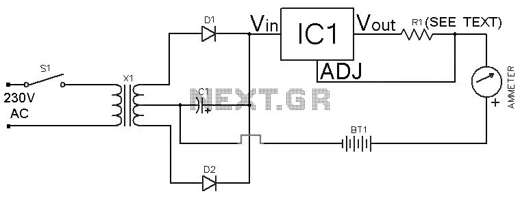
This Ni-Cd battery charger is a circuit utilizing the LM317 regulator IC. The design is straightforward and requires minimal components. By adjusting the value of resistor R1 between 1 ohm and 120 ohms, the charging current can be modified...
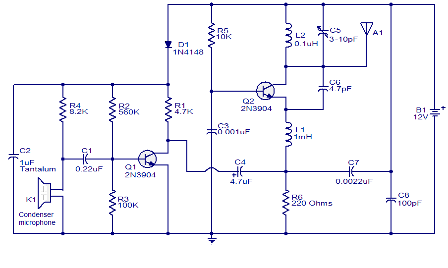
The FM transmitter circuit presented is both stable and simple. With an adaptive antenna, it can achieve a transmission range of approximately 200 meters. This transmitter was developed this year and has yielded positive results. The circuit operates using...
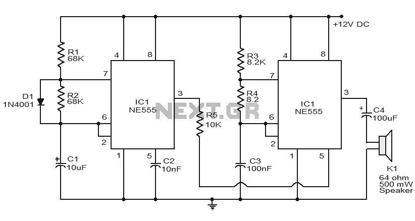
Numerous electronic circuits utilizing the NE555 timer IC have been published, and this is yet another example. The circuit diagram presented illustrates a police siren based on the NE555 timer IC. It employs two NE555 timer ICs, each configured...
This project is a basic code practice oscillator designed for beginners to learn Continuous Wave Morse Code. It utilizes a 555 timer to produce a "dit" or "dah" sound when the key is pressed. The circuit employs a 555 timer...