
LED Blinker with HT-2014M
The LED flasher circuit is designed to provide a visual indication through intermittent illumination of an LED. It utilizes the HT-2014 series of integrated circuits, specifically the HT-2014L and HT-2014M models, to achieve different flashing rates.
The circuit typically consists of the following components: a power supply, an LED, a resistor, a capacitor, and the HT-2014 integrated circuit. The power supply can be a standard DC source, such as a battery, providing the necessary voltage for the circuit operation.
In the HT-2014L configuration, the circuit is designed to produce a flash rate of approximately one flash per second. This is achieved by setting the timing components, namely the resistor and capacitor, to establish a time constant that dictates the on-off cycle of the LED. The HT-2014L operates by charging the capacitor through the resistor until a threshold voltage is reached, at which point the output transitions, turning the LED on. The capacitor then discharges, and the cycle repeats.
For the HT-2014M variant, the circuit is configured to double the flashing rate to approximately two flashes per second. This is accomplished by altering the values of the timing components or by using a different timing configuration within the integrated circuit, which reduces the time constant and thus increases the frequency of the flashing.
The LED is connected in series with a current-limiting resistor to prevent excessive current from flowing through it, which could cause damage. The choice of resistor value is critical to ensure that the LED operates within its specified current range, thereby providing optimal brightness without compromising longevity.
Overall, the simplicity of the LED flasher circuit makes it an excellent project for beginners in electronics, while also serving practical applications in visual signaling and decorative lighting.A very simple LED flasher circuit. With HT-2014L the circuit produces 1 flash per second and the HT-2014M produces 2 flashes per second. 🔗 External reference
Related Circuits
An LED is usually a series resistor needed to ensure that the LED does not get too much power. The disadvantage of such resistance is that the current through the LED and thus the brightness changes as the voltage...

I decided to make a commercial surface mount PC board using the LED2 sensor concept. It is quite sensitive and can track to a few degrees of accuracy in bright sunlight. If a blocking shadow is used the accuracy...
The LED power Meter is a simple RF detector using diodes to charge a capacitor. The voltage developed across the capacitor is indicated by a multimeter set to a low voltage range. The circuit is soldered together without the...
This kit includes fully illustrated instructions and a circuit schematic. Components are adequately spaced for easy assembly and value identification on the board. The circuit board features silk-screened outlines for component placement, and the circuit pads on the solder...
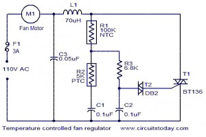
The function for automatically controlling the speed of a fan according to the temperature. Components: BT136 Triac, Capacitor, Resistor, Relay, Fan Motor. This circuit is designed to automatically adjust the speed of a fan based on the ambient temperature. It...

This is a flasher circuit that directly derives power from AC to produce brilliant flashes at a rate of one flash per second. It utilizes a DIAC as the main element. The flasher circuit operates by converting alternating current (AC)...