
LED Chaser
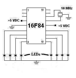
The project utilizes the Microchip PIC16F84 microcontroller, which is an 8-bit device featuring a 13-bit instruction set architecture. The microcontroller operates at a maximum clock speed of 20 MHz, making the choice of a 10 MHz resonator suitable for this application. The resonator provides the necessary clock signal for the microcontroller’s operation, and the built-in capacitors simplify the circuit design by eliminating the need for external components.
The circuit design likely includes essential connections such as power supply pins (Vdd and Vss), which should be connected to the appropriate voltage levels (typically 5V for the PIC16F84). The microcontroller’s GPIO (General Purpose Input/Output) pins can be configured for various functions, including digital input, output, or analog functions depending on the application requirements.
In addition to the resonator, bypass capacitors may be used across the power supply pins to filter out noise and stabilize the voltage supply. The schematic may also include pull-up or pull-down resistors on input pins, depending on the intended use of those pins.
The software for this project is written in Hi-Tech C, a popular compiler for PIC microcontrollers, which allows for efficient coding and easy debugging. The source code, with a ".c" extension, likely contains the main program loop, initialization code, and any interrupt service routines necessary for handling events such as button presses or sensor readings.
Overall, the design and implementation of this project demonstrate a fundamental understanding of microcontroller applications, including hardware interfacing and software development, which are critical skills in electronics engineering.This was my first sucessful project with a PIC chip. I used a 16F84 with a 10MHz resonator with built in caps. Click here to view the source code to this project. The code is written in Hi-Tech C. Click here to download the source code to this project. File has a ".c" extension. 🔗 External reference
Related Circuits
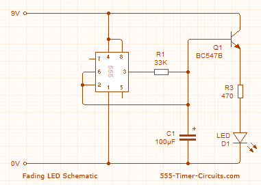
These two circuits create a fading effect for an LED. The first circuit charges a 100µF capacitor, and a transistor amplifies the current entering the capacitor, delivering 100 times this value to the LED through the collector-emitter pins. The...
Here is the schematic for the circuit. Solder all the components onto a perfboard. The drawings may not be very clear. Essentially, the 555 timer generates a pulse. The circuit utilizes a 555 timer IC configured in astable mode, which...
Anyone who has ever dealt with construction of low-voltage-fed inverter realized that this is no easy task. The shrinking supply voltage decreases rapidly transferred power and efficiency. Samokmitající converters fail to provide sufficient power to drive control for the...
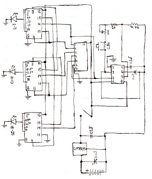
This circuit when used with a 555 timer will cause light emitting diodes to turn on and off more slowly. This will make the LEDs appear similar to incandescent lamps. The described circuit utilizes a 555 timer IC configured in...
The LM3915 is a monolithic integrated circuit that senses analog voltage levels and drives ten LEDs providing a logarithmic 3 dB/step analog display. LED current drive is regulated and programmable, eliminating the need for current limiting resistors. The IC...
This circuit allows for the adjustment of fan speed from a distance, such as from a couch or bed. It utilizes the TSOP1738 infrared receiver module to capture the infrared signals. The circuit operates by employing an infrared remote control,...