
Rotating LED Marquee Hat circuit

The circuit utilizes a 555 timer IC configured in astable mode, which allows it to produce a continuous square wave output. This configuration is commonly used for timing applications, oscillators, and pulse generation. The essential components involved in this circuit include resistors, capacitors, and the 555 timer IC itself.
To assemble the circuit on a perfboard, begin by placing the 555 timer IC in the center of the board. Ensure proper orientation by aligning the notch on the IC with the corresponding mark on the perfboard. Next, connect two resistors in series between the discharge pin (Pin 7) and the threshold pin (Pin 6), with the junction of these resistors also connected to the trigger pin (Pin 2). The values of these resistors will determine the frequency of the output pulse.
A capacitor is connected between the threshold pin (Pin 6) and ground (Pin 1). The capacitor's value, in conjunction with the resistor values, will set the duty cycle of the output waveform. The output pin (Pin 3) provides the square wave signal, which can be used to drive other components or circuits.
Ensure that all connections are soldered securely to prevent any intermittent connections. After completing the assembly, it is advisable to test the circuit with a multimeter or oscilloscope to verify that the output signal is as expected. Adjustments to the resistor and capacitor values can be made to fine-tune the frequency and duty cycle of the output pulse. Proper power supply connections should also be made to the 555 timer, with the VCC pin (Pin 8) connected to the positive supply voltage and the ground pin (Pin 1) connected to the negative supply.Here`s the schematic for the circuit. Solder all the components onto perfboard. Sorry the drawings kind of bad. Basically, the 555 timer sends a pulse.. 🔗 External reference
Related Circuits
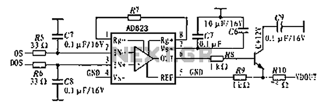
The AD623 is an integrated 3-way amplifier that can operate with either a single or dual supply. It features high common-mode rejection ratio (CMRR) and low voltage drift, along with programmable gain control via an external resistor. All components...
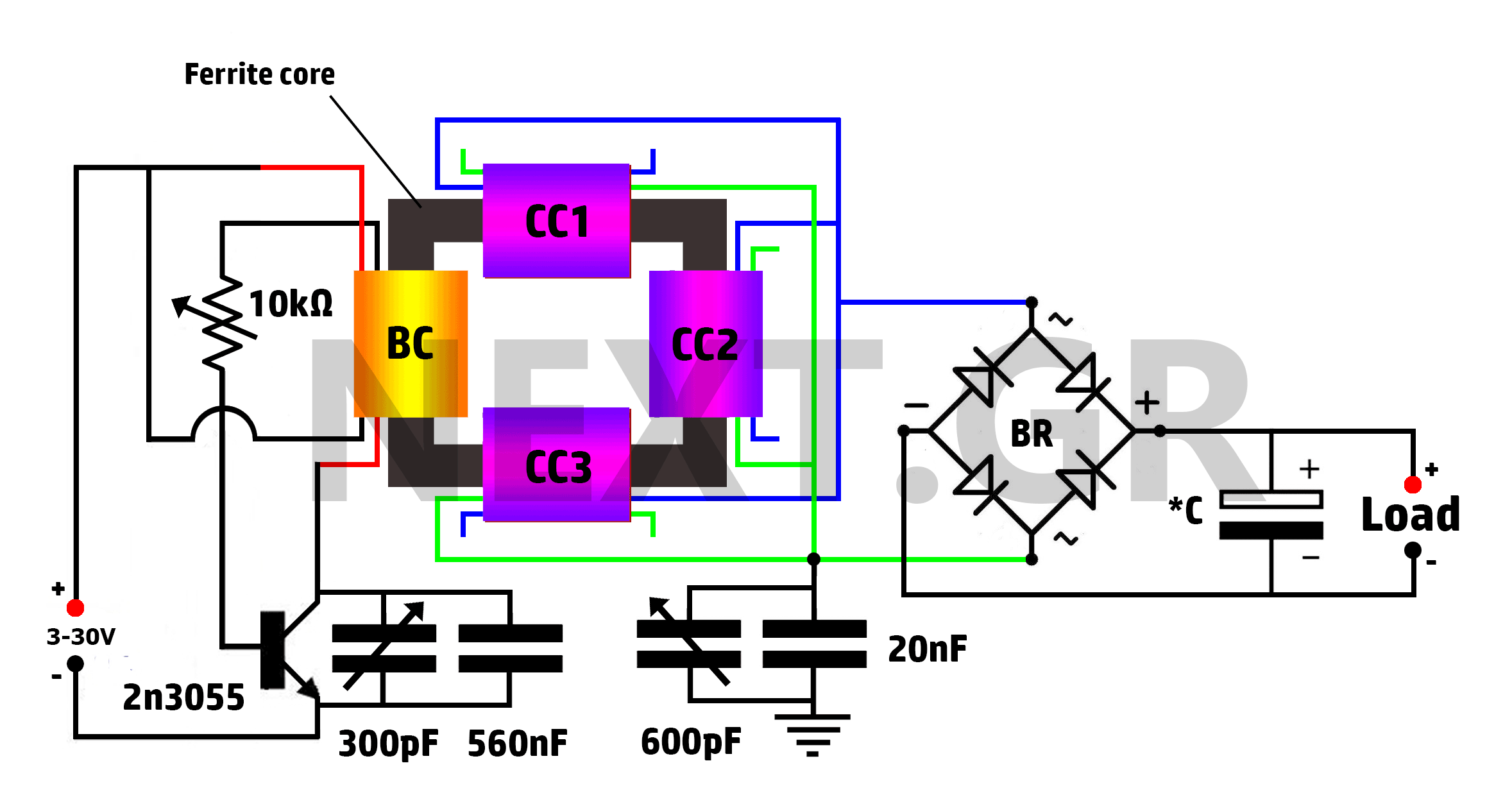
This is a Tesla/joule thief hybrid circuit that its inventor claims can produce 90 times the input power. The circuit can be self-looped and can provide 1050W of power, with only 11.6W looping back to supply the joule thief....
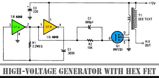
The schematic diagram below illustrates a high voltage generator circuit. This circuit employs a 4049 hex inverter configured as an oscillator, and it can utilize an ignition transformer from an automotive engine. A fly-back transformer may also be suitable....
In applications where a MOSFET is employed to switch a load, incorporating short-circuit or overload protection is straightforward. This can be achieved by utilizing the internal resistance RDS(ON) of the MOSFET, which generates a voltage drop proportional to the...

Any standard oscillator, such as a Colpitts or Hartley configuration, can be utilized to generate the local oscillator (LO) frequency required by the NE602. The NE602 is a versatile integrated circuit commonly used in radio frequency applications, particularly in mixer...
Its based on inductive pickup and very easy to install. Have a look at the pic. (remove LED and connect transistor collector to pin4). I hope it will exactly suits to your tachometer. More: I found your PIC project...