
LED-Circuits 4
The constant current source circuit utilizing the BF256C FET is a practical solution for LED applications, providing a steady output current of 15mA. This design is particularly useful in scenarios where precise current control is necessary, such as in LED lighting applications. The circuit's simplicity allows for easy construction, making it an excellent educational tool for those learning about FET operation and LED characteristics.
The use of a single resistor to limit current in series with an LED chain is a fundamental method that demonstrates Ohm's law and the principles of current limiting. When utilizing a regulated power supply, this approach ensures that the LEDs operate within their safe current ratings, preventing damage and extending their lifespan.
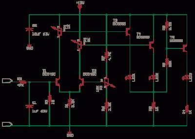
The differential amplifier configuration formed by transistors T1 and T2 is crucial for amplifying small voltage differences, making it suitable for applications requiring precise voltage measurements. The comparators T3, T4, and T5 facilitate the operation of the LED indicators, providing visual feedback based on the input voltage levels. This feedback mechanism is essential for monitoring and controlling circuit behavior.
The inclusion of a zener diode for voltage regulation ensures that the operational amplifier receives a stable supply voltage, critical for consistent performance. The voltage divider created by resistors R2, R3, R5, and R6 is instrumental in scaling down the mains voltage to a manageable level for the circuit's components, allowing for accurate voltage monitoring.
Safety considerations are paramount when working with mains voltage. The circuit's design, which avoids the use of isolation transformers, emphasizes the necessity for skilled construction and adherence to safety protocols. The use of fusible resistors enhances the circuit's reliability by providing a fail-safe mechanism in case of overload conditions.
In summary, this circuit exemplifies a versatile approach to current regulation and voltage monitoring, integrating fundamental electronic principles with practical applications. Proper understanding and careful construction are essential for safe and effective operation.This is a constant current source using a FET. This is the most simple replacement to series resistor to limit current. The N-Channel FET BF256C can give 15mA current. Simple Methods Before you get to use chips, experiment with some methods, which will help you learn about the LEDs better. The first is just One Resistor in series. This is to Limit the max current in a Series LED Chain. If you have a Regulated Supply with a Fixed Voltage, then you can use this method. Let us take a 12V SMPS, Each HB White LED has a drop of Read More This circuit is derived from a Siemens Application Note 1974. This circuit uses common components of today. The circuit is here as it is of high educational value. I have not tested it. You can simulate and test` or wire it up and try` and let me know how it worked. The Circuit is also a simple analog to digital converter. You can use optos in place of LEDs. T1 and T2 make a differential amplifier. T3, T4 and T5 driving the LEDs are comparators. Now to learn more on how they work you have to study circuits at 4QD-TEC Read More This Circuit helps in the monitoring of mains supply voltage.
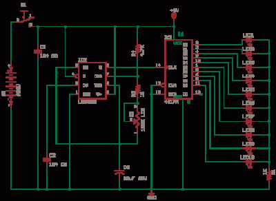
It does not use a isolation step down transformer. This has to be constructed only by skilled people with knowledge of safety requirements. C1 limits the current and drops most of the voltage. The zener regulated supply is for the chip. C2 can be raised to 220uF or more if required. The bar mode display may consume more power. R2-R3-R5-R6 form a voltage divider to get a sample of the input voltage, D11-C3 get the DC value. Adjust R5 preset with a log Plastic tweaker to get the 5th led Read More This Circuit helps in the monitoring of mains supply voltage. It does not use a isolation step down transformer. This has to be constructed only by skilled people with knowledge of safety requirements. C1 0. 47uF can be brought down to 0. 22uF for low LED currents, use high efficiency ultra bright LEDs. C1 should be 440V AC or 630V DC plastic axial yellow, polyester, polycarbonate, polypropylene, metalized film.
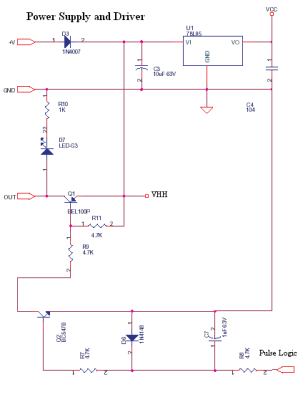
R3-R6-R9-R14-R18 resistor divider determines the LED turn on or threshold switch points, 10M for hysteresis. Adjust R16 preset with a log Plastic tweaker to get the led D2 to turn on when input voltage Read More This is a mains 230V AC load current indicator and is a LIVE CIRCUIT, so take care.
The Resistors have to be a fusible ceramic wire wound. This circuit has been drawn from my memory and i have not tried it out again, just see if it is ok and then try. You should use the fuse of 1A a slow blow if you want but it is very important. You can design the shunt R3 and Fuse rating as required by your load. Note that this circuit is to be put in series with the load like an ammeter. Read More This circuit uses a LM339, a quad comparator. LM339 can work on single or dual supplies, it has a open collector output that can drive 15mA, low power consumption.
The circuit is an untested design but it should work. I did it as many searches were made in my webpages with these keywords. There are many better circuits in the various circuit archives i have linked on the front page, you just have to look around. When you measure the open circuit voltage of a battery with a high impedance DMM (10M), the value may be a bit misleading.
Apply Read More 🔗 External reference
Related Circuits
This LED series will blink alternately. The operation is determined by the NE555 integrated circuit, with transistors used to reinforce each section (20 upper, 20 lower) for optimal performance. The 555 circuit described below functions as a flashing bicycle...
The 555 Astable generates a clock for this circuit, functioning as an oscillator that produces a square wave output at pin 3. This output is counted by the CD4017 decade counter, which creates a running lights effect. The CD4017...
This circuit is a digital panel meter (DPM) featuring an analog bar graph display and a 3.5-digit digital display. The ICL7107 is configured for 200mV input. The U4A operational amplifier (LF353) amplifies the 200mV full-scale input to the required...