
LED-Circuits 7
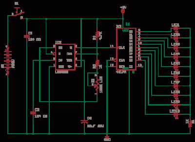
The 555 timer in astable mode operates as a square wave oscillator, generating a continuous signal that can be used for various applications, including light sequencing. In this specific circuit, the output from pin 3 of the 555 timer is fed into the clock input of the CD4017 decade counter. The CD4017 is designed to count pulses and activate its outputs sequentially. With each pulse from the 555 timer, one of the ten outputs of the CD4017 will turn on an LED, creating a visually appealing running light effect. By adjusting the linear potentiometer (R2), the timing of the 555 timer can be altered, thereby controlling the speed at which the LEDs light up.
The monitoring function for the telephone line is achieved through a clever arrangement of diodes and LEDs. The diodes D1 to D4 create a bridge rectifier that allows the circuit to operate correctly regardless of the polarity of the incoming telephone line. LED1 serves as an indicator for a properly functioning line, while LED3 provides feedback about the line's status based on the voltage across the Zener diode. This functionality is crucial for users who wish to avoid interrupting a conversation when attempting to use the phone. LED2 acts as a visual signal for incoming calls, enhancing the usability of the circuit in a multi-phone setup.
In summary, this circuit integrates a 555 timer for oscillation, a CD4017 for counting and sequencing, and a monitoring system for telephone lines, all working together to provide a functional and efficient solution for both visual effects and telephone status indication.The 555 Astable generates a clock for this circuit, an oscillator giving a square wave output at pin 3 which is counted by 4017 to give a running lights effect. The decade counter-divider CD4017 has 10 outputs, for every low to high transition at the clock input, rising edge, the counter advances one LED.
After going one full circle the the first LED lights again and it goes on. You can vary the value of R2 100K Linear potentiometer to make LEDs run fast or slow. The frequency of oscillation of astable 555 is given as f = 1. 44 / Read More This will monitor telephone status without loading the telephone line, this way if you have two phones in parallel you will know if one of them is busy. Connect the two ends of circuit in parallel to phone lines. D1 to D4 make a bridge so that LED`s are powered in correct polarity. LED1 indicates line ok no broken line, LED3 can light only when a 12V Zener breaksdown, this shows if line is busy or free, so that you dont go online when someone is talking on the phone in another room.
LED2 lights on an incoming call ringing Read More 🔗 External reference
Related Circuits
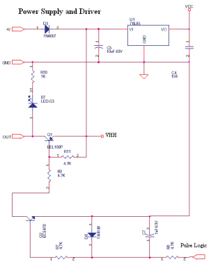
This is a constant current source using a FET. It serves as a simple replacement for a series resistor to limit current. The N-Channel FET BF256C can provide a current of 15mA. Before using integrated circuits, it is advisable...
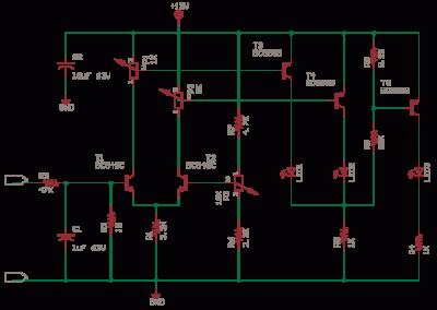
This LED series will blink alternately. The operation is determined by the NE555 integrated circuit, with transistors used to reinforce each section (20 upper, 20 lower) for optimal performance. The 555 circuit described below functions as a flashing bicycle...
This circuit is a digital panel meter (DPM) featuring an analog bar graph display and a 3.5-digit digital display. The ICL7107 is configured for 200mV input. The U4A operational amplifier (LF353) amplifies the 200mV full-scale input to the required...
Warning: include(partials/cookie-banner.php): Failed to open stream: Permission denied in /var/www/html/nextgr/view-circuit.php on line 713
Warning: include(): Failed opening 'partials/cookie-banner.php' for inclusion (include_path='.:/usr/share/php') in /var/www/html/nextgr/view-circuit.php on line 713