
PICAXE 08M control of audio/video cabinet cooling
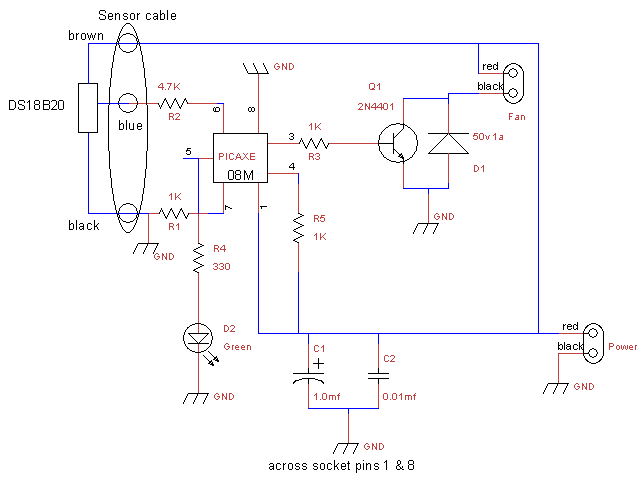
The fan controller circuit operates on a microcontroller-based system designed to monitor and regulate temperature within an enclosed audio/video cabinet. The PICAXE 08M serves as the central processing unit, executing the control logic based on inputs from the DS18B20 temperature sensor. This sensor provides accurate temperature readings, allowing the microcontroller to determine when to activate or deactivate the fan based on predefined temperature thresholds.
The fan is connected to the left terminal block, receiving power from the regulated supply, which also powers the microcontroller. The choice of a 12-volt fan running at a reduced voltage of 5.2 volts ensures a quieter operation while still maintaining sufficient airflow to manage heat dissipation effectively. The fan's airflow rate of 11 CFM is adequate for the cabinet's size, preventing excessive heat buildup above the television.
The green LED indicator provides visual feedback about the system's operational status and serves as an approximate temperature gauge, allowing users to monitor the system's performance at a glance. The inclusion of screw terminals for connections enhances the reliability and ease of installation, facilitating straightforward wiring for the fan, power supply, and temperature sensor.
Overall, this fan controller design exemplifies a practical solution for thermal management in compact electronic enclosures, ensuring the longevity and performance of audio/video equipment while maintaining user-friendly features and efficient operation.This is a fan controller for an audio/video cabinet. It uses a PICAXE 08M and a DS18B20 temperature sensor. The fan is turned on at 30 degrees C (~86 F) and off at 28 degrees C (~82 F). The green LED is the activity indicator and also serves as a "ballpark" temperature indicator. All off-board connections are made via screw terminals. The lef t terminal block for the fan, the bottom block for power, the right terminal block for the DS18B20. This project was initiated when we replaced a 12-year-old TV with a new 26" HD-capable LCD TV (happy 41st anniversary to us ;-) This TV was the largest that would fit in the existing corner cabinet (which is the largest cabinet that will fit between the brick fireplace and the window on the side wall). After moving the DVD player shelf up, there was still less than 2" (50mm) clearance above the new TV.
Initial testing (hand on the upper shelf) indicated this was not enough for adequate ventilation. A thermometer verified this with a reading of just over 114 degrees F (~46 C) - a rise of 26 degrees F above room temperature. The fan is a 12 volt, 11CFM unit running off the regulated 5. 2 volt, 1. 2 amp supply that also powers the PICAXE board. The lower voltage reduces the fan speed (and noise) but the fan still delivers enough air flow to limit the temperature rise at the hottest point (directly above the TV) to 12 or 14 degrees F.
A maximum cabinet temperature of 92 degrees F (33 C) in a room that`s at 78 degrees F (~25 C) is certainly acceptable. This was installed on 24 September 2006. After a week or so of testing, the circuit board will be placed in a case with a transparent or translucent cover (so the LED will remain visible).
Note that US/metric conversions are approximate - I`m not processing silicon wafers, just preventing overheating ;-) 🔗 External reference
Related Circuits
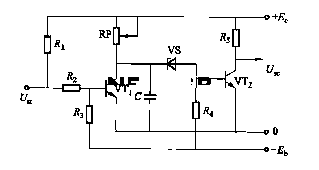
The circuit is a rechargeable short delay control for a conducting pipe, featuring two adjustment potentiometers (RP) that enable the delay time to be set from several hundred milliseconds to several seconds. The rechargeable short delay circuit is designed for...
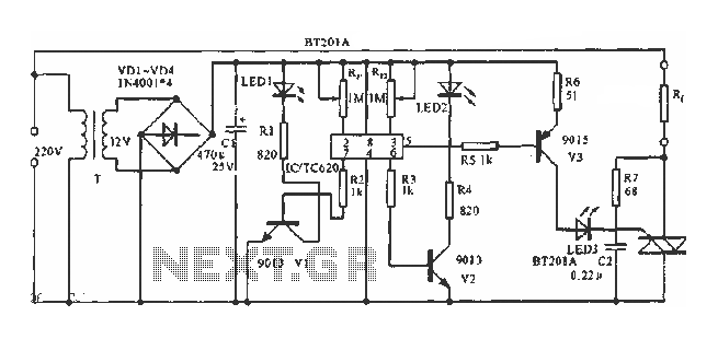
The circuit utilizes a built-in temperature sensor to control the triac TC620 for temperature regulation. The adjustment circuit consists of resistors Rp1 and Rn, which can be modified to set both the lower and upper temperature limits. LED1 illuminates...
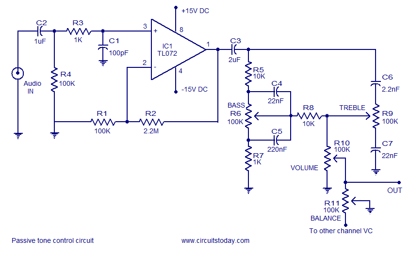
Tone control circuit utilizing an operational amplifier and a Baxandall passive tone control configuration. The overall gain is 25 dB, with a boost and cut capability of 20 dB. The circuit is powered by a dual 15V supply. The tone...
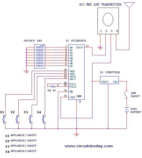
This project outlines a simple remote control system utilizing RF communication without the use of a microcontroller. The remote is designed for various home appliances such as televisions, fans, and lights, providing significant convenience by allowing operation from a...
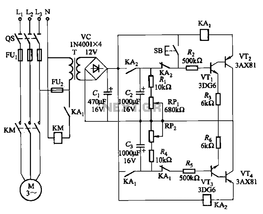
The circuit illustrated in Figure 3-79 consists of two delay circuits. The RPi adjustment potentiometer and RP2 can be modified to control the duration of the motor operation, allowing for arbitrary adjustments within a specified time frame. The circuit comprises...
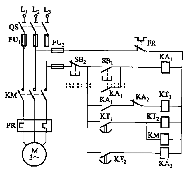
The circuit illustrated in Figure 3-76 employs two time relays, KTi and KTz, to manage the operation and downtime of a motor. The circuit utilizes two time relays to provide precise control over the motor's operational cycles. Relay KTi is...