
Liquid level controller circuit diagram 1 -
The liquid level controller circuit is designed to monitor and manage the liquid levels within a specified container, ensuring that the levels remain within predetermined thresholds. The power supply circuit is essential for providing the necessary voltage and current to the entire system. It begins with a power switch (S1) that allows the user to turn the circuit on or off. The power transformer (T) steps down the voltage from the mains supply to a lower voltage suitable for the circuit operation.
The bridge rectifiers (UR1 and UR2) convert the alternating current (AC) output from the transformer into direct current (DC), which is then smoothed by the filter capacitors (C1 and C2). These capacitors help to reduce voltage ripple, ensuring a stable DC voltage is supplied to the control circuit.
The level detection control circuit plays a critical role in sensing the liquid level. It utilizes test electrodes (labeled a to c) that are placed at various heights within the container. These electrodes detect the presence or absence of liquid and send corresponding signals to the control unit. The control unit processes these signals to determine if the liquid level is above or below the set points. If the liquid level falls below a certain threshold, the control circuit can activate a pump or valve to refill the container, or if it rises above the maximum level, it can activate a drain mechanism.
This circuit can be further enhanced with additional features such as visual indicators (LEDs) to show the status of the liquid level, alarms for low or high levels, and even remote monitoring capabilities using wireless communication modules. The implementation of microcontrollers can also provide more sophisticated control algorithms, allowing for greater flexibility and accuracy in managing liquid levels. Overall, the liquid level controller circuit is a vital component in various applications, including industrial processes, water treatment facilities, and home automation systems.The liquid level controller circuit consists of the power supply circuit and level detection control circuit, and it is shown as the chart. Power supply circuit consists of the power switch S1, power transformer T, bridge rectifiers UR1, UR2 and filter capacitors C1, C2.
Liquid level detection control circuit is composed of the test electrodes a ~ c, control.. 🔗 External reference
Related Circuits
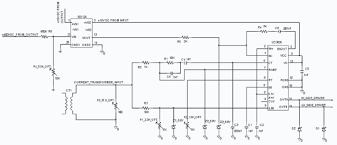
The UC3825 IC, manufactured by Texas Instruments, is a high-speed pulse width modulation (PWM) controller that serves as the central processor for a DC/DC converter control circuit. This circuit primarily consists of three integrated circuits: the UC3825BN, ISO124, and...
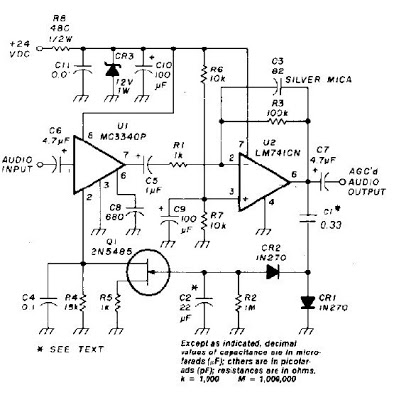
An audio signal applied to VI is passed through the operational amplifier 741, U2. After being amplified, the output signal V2 is sampled and applied to a negative voltage doubler/rectifier circuit composed of diodes CR1 and CR2, along with...
This page features a circuit that has twenty open collector outputs that turn on one at a time in a continuous sequential manner. The circuit utilizes the 74LSxx family of TTL integrated logic devices. The circuits are designed to...
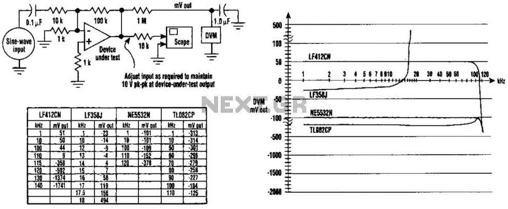
The DC values of op-amp offsets cannot always be assumed to remain constant when delivering AC outputs. No device is perfectly symmetrical in terms of maximum positive slew rate compared to maximum negative slew rate. As a result, there...
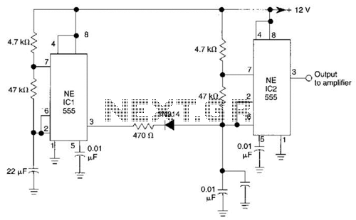
IC1 generates a pulse that modulates the 1000-Hz tone generated by IC2. This circuit can be used to generate warning or alert signals. The circuit described consists of two integrated circuits (ICs), where IC1 is responsible for generating a pulse...
A high-input-resistance op-amp, a bridge rectifier, a microammeter, and a few other discrete components are all that are required to realise this versatile circuit. This circuit can be used for measurement of dc, ac rms, ac peak, or ac...