
LED Countdown Timer with AT89C2051

The countdown LED timer circuit is designed to provide a user-friendly interface for timing applications, suitable for various tasks such as cooking, exercise, or any activity requiring time management. The core of the timer is based on a microcontroller, which handles the countdown logic and user input.
The circuit includes three push-button switches: one for setting the minutes, one for setting the seconds, and a start/stop button. The minute and second buttons are connected to the microcontroller's GPIO (General Purpose Input/Output) pins, allowing the user to increment the respective values. A display unit, typically a 7-segment LED display or an LCD, is used to visually indicate the remaining time in a clear format.
The microcontroller is programmed to count down from a maximum of 99 minutes and 59 seconds. The countdown process is initiated by pressing the start button, which triggers the microcontroller to begin decrementing the time at one-second intervals. An internal timer or clock function within the microcontroller ensures accurate timing.
When the countdown reaches zero, the microcontroller activates a loud buzzer, providing an audible alert to signal the end of the countdown. The buzzer is typically a piezoelectric type, known for its loud sound output, making it effective for alerting users in noisy environments. The alarm can be silenced by pressing the start/stop button, which also serves to halt the countdown if pressed during the timing process.
Power for the circuit is usually supplied by batteries or an external power source, ensuring portability and ease of use. Additional components may include a resistor for current limiting on the LED display and capacitors for power stabilization. The circuit should also incorporate debouncing logic for the push buttons to prevent false triggering due to mechanical noise.
Overall, the simple count-down LED timer circuit is a practical solution for time management, combining ease of use with effective timing capabilities.A simple count-down LED timer that counts in minutes and seconds. Three buttons below the LED provide control of the unit, allowing you set the desired countdown time in minutes and seconds and a start/stop button. Completion of the countdown is indicated by an alarm that starts when the countdown has finished and the display reads zero.
The alarm is stopped by pressing the start/stop button. Counts down from up to 99 minutes 59 seconds Loud buzzer 🔗 External reference
Related Circuits
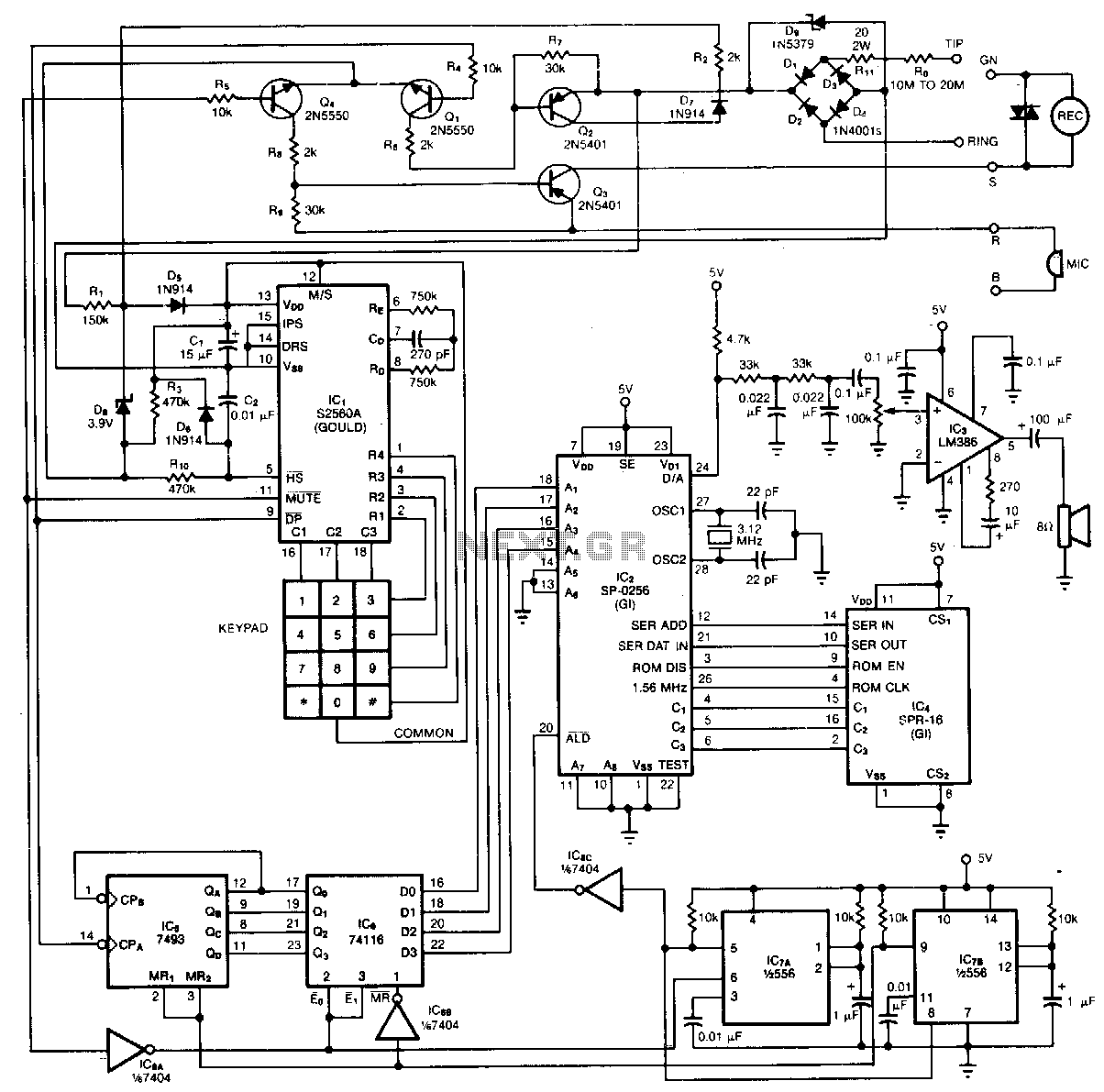
By vocalizing the numbers and symbols of its keypad, the phone provides audible confirmation that is useful to the blind. The serial interface, 2 K-byte x 8-bit ROM (IC4) stores programmed sequences of instructions that are executed by the...
This circuit is a double direction flash. Similar to Digital Ping-Pong 1, there is a movement of a lit dot, up and down along the LED's length. When the D16 lit the situation changes and there is a reverse...
The TLD 5085EJ is a smart LED buck converter featuring an integrated power switch, designed to drive a load current of up to 1.8A with excellent line and load regulation. This device is specifically intended for stepping down input...
This timer is intended for individuals seeking to achieve a tan while minimizing excessive exposure to sunlight. A rotary switch adjusts the timer based on six categorized photo-types. A photoresistor modifies the preset time value in relation to sunlight...
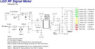
This device is a high-quality RF signal meter utilizing the Analog Devices AD8313 logarithmic detector integrated circuit (IC), which operates within the frequency range of 0.1 GHz to 2.5 GHz. It can detect signals as low as -80 dBm....
The article describes a simple and very cheap to drive white, blue or UV LEDs, used for example in small lamps and testers. The cost of components shall not exceed CZK 10. Converters for white LED has been on...