
Mc68hc908ey16 Controlled Robot Using The Lin Bus

The system oscillator, specifically a crystal or ceramic oscillator, utilizes a combination of passive components, including resistors, capacitors, and inductors, to create a stable frequency output. The equivalent circuit typically consists of a parallel resonant circuit formed by a crystal or ceramic element, which exhibits piezoelectric properties.
In such an oscillator circuit, the crystal or ceramic resonator is represented by its equivalent series resistance (ESR), resonant frequency, and load capacitance. The resistors are employed to set the biasing conditions and stabilize the operating point of the oscillator, while capacitors are used for coupling and filtering purposes. Inductors may also be included to enhance the frequency stability or to form part of a feedback loop.
The oscillator can be configured in various topologies, including Colpitts or Clapp oscillator configurations, which utilize the aforementioned components to achieve the desired oscillation characteristics. The feedback loop, essential for sustaining oscillations, is typically formed by connecting the output of the amplifier back to the input through a network of these passive components.
Overall, the design of a crystal or ceramic oscillator circuit requires careful consideration of component values to ensure precise frequency generation and stability, making it suitable for applications in clocks, timers, and various electronic devices where accurate timing is critical.System Oscillator Crystal/Ceramic Oscillator. The following circuit combination of resistors, capacitors and inductors depicts an equivalent cir- cuit for a crystal or ceramic Oscillator 🔗 External reference
Related Circuits

The microcontroller design features the microcontroller (MCU) in hibernation mode, which can only be awakened by a pulse (high-low-high) signal on the reset pin (active low). An accelerometer or an external real-time clock (RTC) serves as the wake-up source....
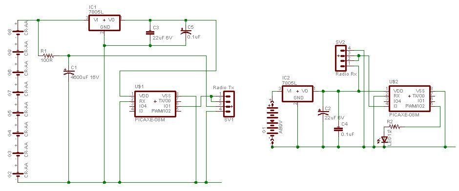
A water tank, dam, or gate can be monitored for vehicle detection without the need for wired connections through the garden. This guide demonstrates how to transmit data reliably over a distance of 500 meters using PICAXE microcontroller chips...
The circuit has been designed for telephone apparatus to indicate an incoming call as it rings using an LED for visual indication. BC550, an NPN general-purpose transistor, is utilized in the design. The circuit operates by detecting the ringing voltage...
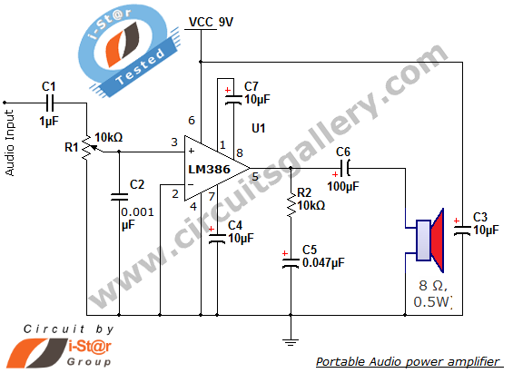
The i-St@r presents a simple mini audio amplifier circuit schematic utilizing the LM386 low voltage audio power amplifier IC. This circuit is designed to power medium-sized speakers from a music player that typically drives only earphones (LM386 headphone). The...
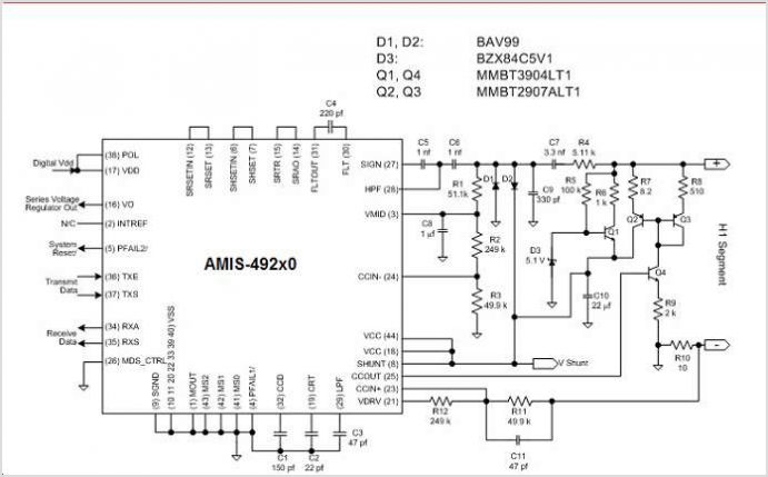
The AMU2481 Audio Mixer is a digital real-time signal processor utilizing NMOS technology, available in a 24-pin DIL plastic package or a 44-pin PLCC package. It is designed for the digital processing of both TV audio information and digital...
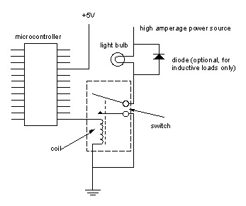
Digital output from a microcontroller is typically a low-amperage signal. For example, when a pin is set HIGH on the microcontroller (in Wiring/Arduino, it is digitalWrite(somePin, HIGH);), the voltage from that pin is usually +3.3V or +5V, with the...