
resistors calculating resistance for LED strips to use as parking lamps and turn signals
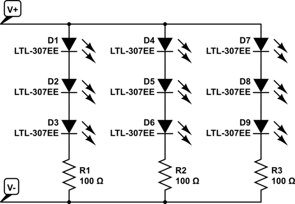
The installation of LED strips in automotive tail lamps presents a modern solution to enhance visibility and aesthetics. The LED strips, chosen for their length and density, will be cut into segments to create three-LED groups. This segmentation is crucial for maintaining uniform brightness and ensuring that the LED strips fit seamlessly within the existing housings.
The circuit design requires careful consideration of voltage and current to ensure the LEDs operate within their specified limits. The use of two diodes serves a dual purpose: one diode will protect the circuit from reverse polarity on the parking lamp line, while the second diode will do the same for the turn signal/brake line. Selecting the appropriate diodes is essential; typically, 1N4001 or similar silicon diodes rated for at least 1A and 50V will suffice for automotive applications.
The resistor in the circuit is critical for reducing the voltage supplied to the LEDs to approximately 7V. To calculate the resistor value, the following formula can be used:
\[ R = \frac{(V_{supply} - V_{LED})}{I_{LED}} \]
Where:
- \( V_{supply} \) is 13.8V,
- \( V_{LED} \) is the forward voltage drop of the LED (usually around 2V for standard LEDs),
- \( I_{LED} \) is the desired current through the LED (typically between 20mA to 30mA).
For example, if the forward voltage drop of the LED is 2V and the desired current is 20mA (0.020A), the calculation would be as follows:
\[ R = \frac{(13.8V - 2V)}{0.020A} = \frac{11.8V}{0.020A} = 590 \Omega \]
A standard resistor value of 560Ω or 620Ω could be used, depending on availability and desired brightness.
In summary, this project involves a systematic approach to converting conventional tail lamps to LED technology, ensuring that proper components are selected to achieve the desired functionality while maintaining safety and efficiency in the automotive electrical system.Installing LED strips in car`s tail lamps to convert it from conventional bulbs to LEDs. This is the product I`m planning on working with and I need a length of 16", 15" and 14" to make then look correct in my housings. When I did the math the 19. 7" strips have about 1. 5 LEDs per inch and need to be segmented into 3 LED groups so I may have to get creative with the placement.
Ffom what I understand I need 2 diodes and a resistor. One diode on the parking lamp power, and one on the turn signal/brake power and then a resistor on the parking lamp wire to step down the voltage enough to make them dim enough to use as a parking lamp and distinguish it from the brighter turn/brake lamps. Does anyone know what size resistor and what size diode to use in this project The voltage, with the car running, is around 13.
8V to the rear lamps. I figure it should be running around 7V to the LEDs to light them as parking lamps. 🔗 External reference
Related Circuits

The Spartan-3 board features eight LEDs connected to FPGA I/O pins, with the cathode of each LED connected to ground through a 330-ohm resistor. To illuminate a specific LED, the corresponding FPGA control signal must be driven to a...

This circuit is designed for general-purpose use with a large LED display utilizing SPI serial interfacing. It employs a serial-in-parallel-out shift register, specifically the 74HC595, to receive serial data from a microcontroller board. The schematic wiring indicates that SER...
This circuit charges two NiCad cells with a constant current and features dual charging rates, voltage cutoff, and an audible alarm. The circuit is powered. This circuit is designed to efficiently charge two nickel-cadmium (NiCad) cells, utilizing a constant current...
After collecting several white LEDs from damaged mobile phones, a project was initiated to construct an LED searchlight. There are two approaches to achieve this: the first is a basic method, which involves connecting white LEDs directly to a...
Four observations regarding the Joule Thief AA battery LED circuit. The schematic of the LED circuit illustrates the power source (V1), which symbolizes a depleted battery with only 1 volt remaining and an internal resistance. The Joule Thief circuit is...

A high-input-resistance operational amplifier (op-amp), a bridge rectifier, a microammeter, and several discrete components are necessary to implement this versatile circuit. This circuit can measure DC, AC RMS, AC peak, or AC peak-to-peak voltage by simply altering the resistor...