
LED display driver circuit a
The LED driver circuit operates by controlling the current flowing through the LED array, ensuring optimal brightness while preventing damage due to excessive current. The integrated circuits 7447A or 74247 are commonly used in applications requiring a binary to seven-segment decoder/driver, making them suitable for driving the display. The arrangement of the LEDs allows for the representation of numerical values, with the additional LED serving as a decimal point for enhanced readability.
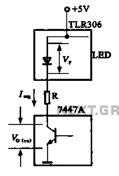
In this configuration, the 5V power supply is essential for powering the entire circuit. The current-limiting resistor is a critical component, as it regulates the current flowing through the LEDs. The selection of a 100Ω resistor provides a safe operating current of approximately 27 mA, which is well within the safe limits of the LEDs, ensuring longevity and consistent performance. Proper heat dissipation measures should also be considered, particularly for the driving transistor, to maintain its performance and prevent thermal failure.
In summary, this LED driver circuit is a well-designed solution for driving high-brightness LEDs in digital displays, offering a reliable operation with appropriate current control and safety measures in place. As shown in Figure is a large high-brightness LED driver circuit for a sufficient drive current, integrated circuits using a 7447A or 74247. Digital display tube has eight ligh t-emitting diodes, seven for digital display, a decimal point for displaying. Driver integrated circuits and light emitting diode equivalent circuit as shown in (a), in the display state. 5v power supply by light-emitting diodes and current limiting resistor R connected to the collector of the driving transistor pole.
For the safety circuit, the current to the light emitting diode is selected according to the desired current limiting resistor, the maximum current of the light emitting diode 35 mA, each having some margin is set to 30 mA, the light emitting diode drop removing 2V, and the driving transistor drop 0.V guide escape when current limiting resistor voltage drop of about 2.7 V, R V // 2.7 V/30 mA. R 90 0, and thus the election of La 100 Q.
Related Circuits
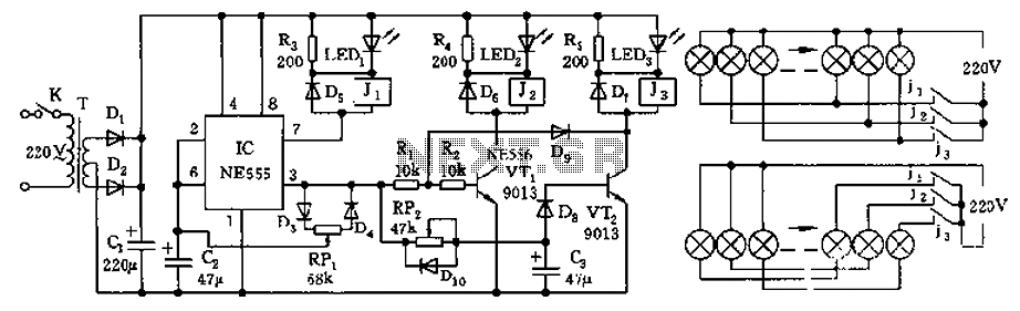
The controller features a buck rectifier circuit utilizing a 555 multivibrator, designed for controlling approximately 220V, 5W low-power parallel lights or 6 to 12V small bulb series. The 555 timer, along with components D3, D4, RP1, and C2, forms...
Have you ever attempted to copy a commercially produced video only to end up with a distorted and jumpy image? If so, then you have run afoul of MacroVision. MacroVision is the most popular copy protection scheme used on...
This is a driver circuit for a nixie tube. The circuit utilizes the 2N3684 transistor as the nixie tube driver due to its Vp rating of 2-5 volts, which ideally matches TTL-DTL logic levels. The nixie tube driver circuit is...
The LM380 is a power audio amplifier designed for consumer applications. To minimize system costs, the gain is internally fixed at 34 dB. It features a unique input stage that allows for ground-referenced input signals. The output automatically self-centers...
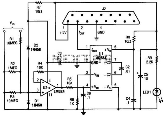
The adapter comprises a voltage-to-frequency converter integrated with a signal conditioning and protection circuit. J2 interfaces with the game port of a personal computer. Additional software references are available for use with this circuit. The voltage-to-frequency adapter functions by converting...
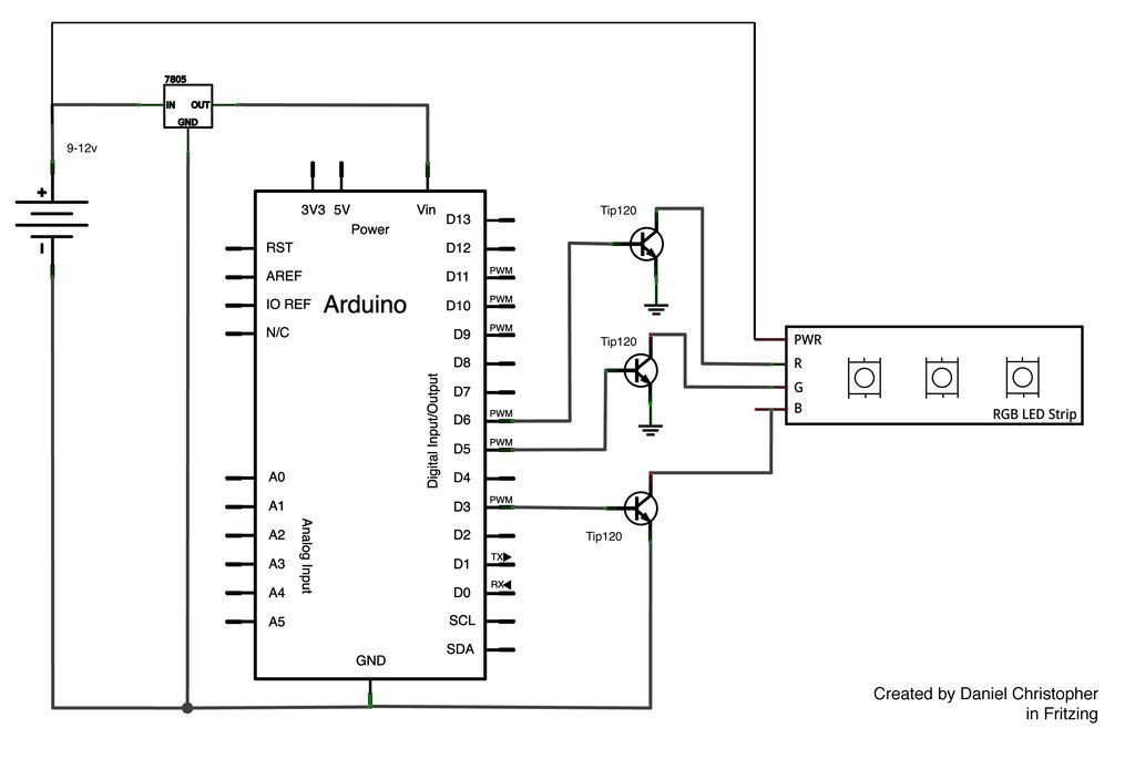
This document outlines the assembly of a circuit designed to pulse width modulate (PWM) a high-power RGB LED strip and program an Arduino to cycle through various colors. The high-power range is specified as 9-12 volts. The procedure includes...