
Dvm Adapter For Pc Circuit
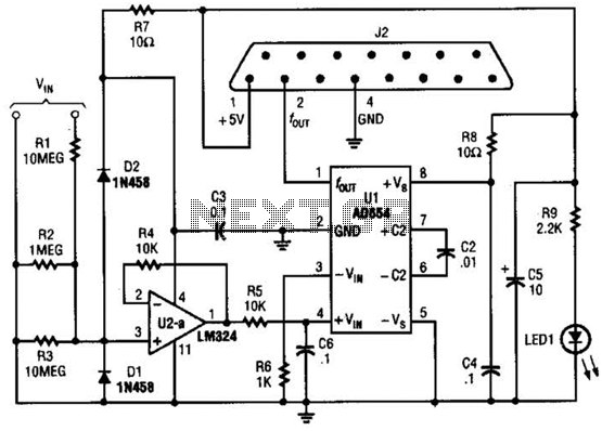
The voltage-to-frequency adapter functions by converting an input voltage signal into a corresponding frequency output. This is achieved through a series of electronic components that ensure accurate conversion while maintaining signal integrity. The signal conditioner enhances the quality of the output signal by filtering noise and amplifying the desired signal, thereby improving the overall performance of the circuit.
The protection circuit is designed to safeguard the adapter from potential overvoltage and overcurrent conditions that could arise from the connected game port. This is crucial in preventing damage to both the adapter and the PC. Typically, this protection circuit may include components such as diodes, fuses, or transient voltage suppressors that react to fault conditions.
The J2 connector serves as the interface between the adapter and the PC's game port, allowing for seamless communication and data transfer. The pin configuration of J2 must align with the game port specifications to ensure compatibility. The adapter's design may also consider the electrical characteristics of the game port, such as signal levels and impedance, to optimize performance.
For users looking to implement this circuit, reference materials provide guidance on the appropriate software to facilitate interaction with the adapter, ensuring that the voltage-to-frequency conversion can be effectively utilized in various applications. This integration of hardware and software enhances the functionality of the adapter, making it suitable for a range of projects within the realm of electronics and computer interfacing. The adapter consists of a voltage to frequency adapter with a signal conditioner and protection circuit. J2 connects to the game port of a PC. See reference listed for software for use with this circuit. 🔗 External reference
Related Circuits
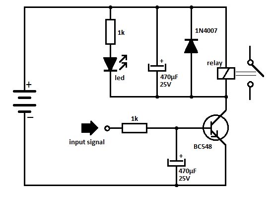
One of the serious problems in relay-operated circuits is the relay clicking or chattering during the on/off operation of the relay driver transistor. This issue can lead to unreliable circuit performance and may cause premature wear of the relay...

This gated 1-kHz oscillator provides press-to-turn-off functionality, along with waveforms available at the output of pin 3 and across capacitor C1. The gated 1-kHz oscillator circuit is designed to generate a square wave output at a frequency of 1 kHz....
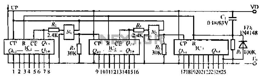
The CD4017B input signal is applied to the CP triggering pin. A pulse signal is sent through the IC, resulting in a straight-through output signal. The coupling device is used to control the input signal. When the power is...
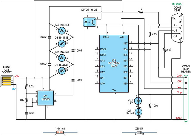
A small biped walker constructed from 2mm plywood, powered by two RC servos. It utilizes the widely available and programmable flash microcontroller PIC16F84. This simple circuit is designed to program the PIC16F84 and similar flash memory components. The project...

This circuit diagram of a digital clock utilizes six common anode seven-segment displays to indicate the time. It does not require microcontrollers or PICs for operation. The circuit operates using the MM5314 integrated circuit, functioning at either 50 Hz...
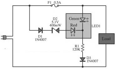
This circuit is designed to monitor the performance of the equipment. It includes a fuse check feature. The circuit is compact and can operate with various power supply voltages. It utilizes a two-color LED, which is of the common...
Warning: include(partials/cookie-banner.php): Failed to open stream: Permission denied in /var/www/html/nextgr/view-circuit.php on line 713
Warning: include(): Failed opening 'partials/cookie-banner.php' for inclusion (include_path='.:/usr/share/php') in /var/www/html/nextgr/view-circuit.php on line 713