
Lead Acid Battery Charger with LED indicator
The circuit functions as a precision voltage source that adapts its output based on the ambient temperature. The core component, the LM350, is a versatile voltage regulator capable of delivering up to 3 amps of current. Its output voltage is adjustable via a potentiometer (P1), allowing for fine-tuning between 13.5V and 14.5V, which is crucial for applications requiring precise voltage levels for battery charging.
The temperature sensor, implemented with a transistor (Q1), introduces a negative temperature coefficient into the circuit. This characteristic is significant because it ensures that as the temperature increases, the output voltage decreases, thus compensating for the temperature effects on battery performance. The temperature coefficient of -8mV/°C is achieved through the configuration of resistors (R3 and R4) that form a voltage divider, influencing the base of the transistor. This configuration amplifies the inherent temperature sensitivity of the transistor, which has a coefficient of -2mV/°C.
To safeguard the circuit against unwanted battery discharge when the input power is absent, a diode (D1) is employed. This diode is rated for 100V and 3A, providing robust protection against reverse current. Additionally, a second transistor (T2) is utilized to ensure that the system remains inactive during power loss, preventing any potential damage to the battery.
The inclusion of a cooling rib for Q1 is essential to maintain accurate temperature readings and prevent self-heating that could skew the voltage output. For optimal performance, the sensor should be positioned in close proximity to the battery to accurately reflect its temperature. The presence of an LED (D2) provides a visual indication of input power, enhancing the usability of the circuit.
Overall, this circuit is a well-engineered solution for battery charging applications, combining precision voltage regulation with temperature compensation features to enhance battery life and performance. Proper component selection and placement are critical to ensure the circuit operates as intended.The above circuit is a precision voltage source, and contains a temperature sensor with a negative temperature co?ficient. Meaning, whenever the surrounding or battery temperature increases the voltage will automatically decrease.
Temperature co?ficient for this circuit is -8mV per °Celcius. A normal transistor (Q1) is used as a temperature sensor. This Battery Charger is centered around the LM350 integrated, 3-amp, adjustable stabilizer IC. Output voltage can be adjusted with P1 between 13.5 and 14.5 volt. T2 was added to prevent battery discharge via R1 if no power present. P1 can adjust the output voltage between 13.5 and 14.5 volts. R4's value can be adjusted to accommodate a bit larger or smaller window. D1 is a large power-diode, 100V PRV @ 3 amp. Bigger is best but I don't recommend going smaller. The LM350's 'adjust' pin will try to keep the voltage drop between its pin and the output pin at a constant value of 1.25V. So there is a constant current flow through R1. Q1 act here as a temperature sensor with the help of components P1/R3/R4 who more or less control the base of Q1.
Since the emitter/base connection of Q1, just like any other semiconductor, contains a temperature co?ficient of -2mV/°C, the output voltage will also show a negative temperature co?ficient. That one is only a factor of 4 larger, because of the variation of the emitter/basis of Q1 multiplied by the division factor of P1/R3/R4.
Which results in approximately -8mV/°C. To prevent that sensor Q1 is warmed up by its own current draw, I recommend adding a cooling rib of sorts. (If you wish to compensate for the battery-temperature itself, then Q1 should be mounted as close on the battery as possible) The red led (D2) indicates the presence of input power.Depending on what type of transistor you use for Q1, the pads on the circuit board may not fit exactly (in case of the BD140).
🔗 External reference
Related Circuits
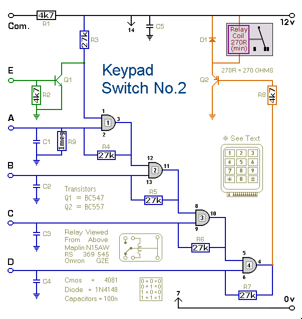
This is a simplified version of the 4-Digit Keypad Controlled Switch. The design has been modified to reduce the complexity of the circuit and the number of components required. Consequently, the code may be somewhat less secure; however, it...
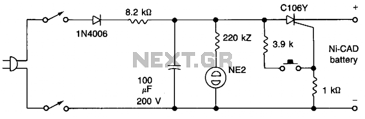
This zapper clears internal shorts in nickel-cadmium batteries by burning them away. CAUTION: The negative battery terminal is connected to one side of the AC line. For safe operation, use a 1:1 isolation transformer. The described device, commonly referred to...
The LED power Meter is a simple RF detector using diodes to charge a capacitor. The voltage developed across the capacitor is indicated by a multimeter set to a low voltage range. The circuit is soldered together without the...
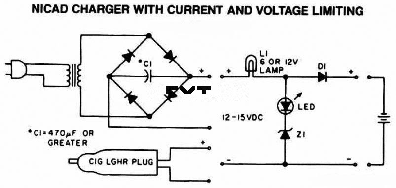
The following diagram is the schematic of a Ni-CAD battery charger circuit, which includes current and voltage limiting features to extend the battery's lifespan. The lamp L1 will illuminate brightly, and the LED will be off when the battery...

The battery should charge up to 14 volts. A reading of 10.7 volts indicates that one cell is shorted. A good way to diagnose this further is to look at the water level in the cells. The shorted cell...

This schematic represents a radio receiver circuit based on the TDA7088T, which is suitable for use in mono portable and pocket radios. The TDA7088T is a bipolar integrated circuit designed to operate with a minimal number of peripheral components...