
LED Flasher IIV
The described circuit is a basic flashlight design that utilizes a transistor-based switching mechanism to control an LED output. The circuit is powered by a voltage supply ranging from 4.5V to 12V, allowing for flexibility in power source selection.
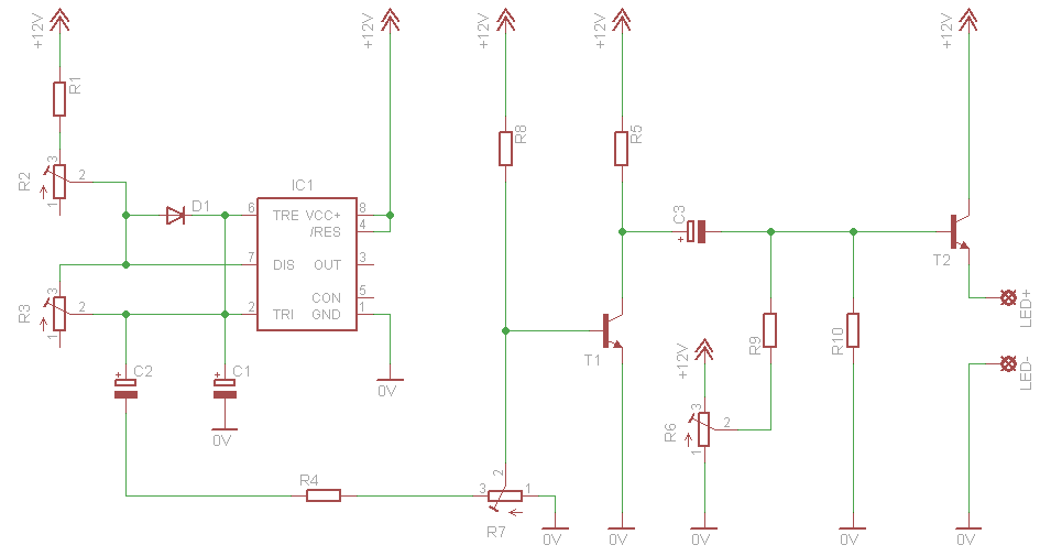
The resistors R1 and R2, each valued at 150 kOhm, are likely used for biasing the transistors T1 and T2, which are BC 547B NPN transistors. These transistors function as switches, allowing current to flow through the LED (D2) when activated. The resistor R3, valued at 2.7 kOhm, may serve as a current-limiting resistor for the LED, ensuring that it operates within safe limits to prevent damage due to excess current.
The capacitor C1, with a value of 2.2 µF and a voltage rating of 16V, is likely included for stability and filtering purposes, smoothing out any voltage fluctuations that may occur during operation. The diode D1, a 1N4148, is utilized for its fast switching capabilities and may be included to protect the circuit from reverse voltage or to manage current flow effectively.
R4 is listed as 100 ?, which seems to be an incomplete specification and should be clarified for proper circuit integration. The red LED (D2) will illuminate when the circuit is powered and the transistors are activated, providing the intended flashlight functionality.
This circuit can be constructed in approximately half an hour, making it suitable for beginners or educational purposes. The simplicity of the design allows for easy modifications, such as replacing the LED with other types of light-emitting diodes or adjusting resistor values to change brightness levels. Overall, the design provides a practical example of using transistors in a basic electronic application.This is a simple design of a single flashlight. This small circuit is within a half hour to build. The circuit operates from 4.5 to 12 V. Of course it is possible other than to drive an LED. R1, R2 = 150 kOhm R3 = 2.7 kOhm R4 = 100 ? C1 = 2.2 V ?F/16 D1 = 1N4148 D2 = LED red T1, T2 = BC 547B 🔗 External reference
Related Circuits
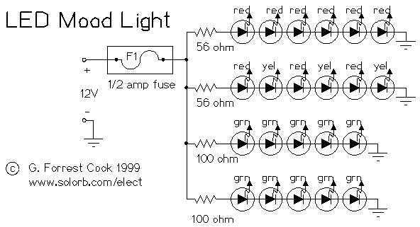
Power this project from sunlight with a CirKits solar power circuit board kit. Other LED lamp circuits can be seen at FC's Solar Circuits, another interesting LED project is my 13 Color LED Rainbow. This circuit makes a nice...
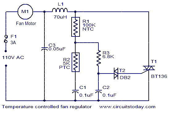
This fan regulator circuit automatically controls the speed of a fan based on temperature. It utilizes two thermistors (R1 and R2) for temperature sensing. The operation is similar to previously published designs, with thermistors replacing the potentiometer. As the...
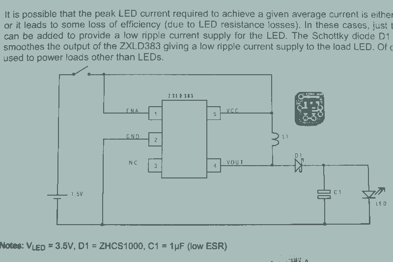
It may seem that due to the numerous flashlight projects undertaken, there is a significant collection of lights. The inductor can be altered to set the current level, but the total current fluctuates with the battery supply, decreasing as...
This circuit allows for the adjustment of fan speed from a distance, such as from a couch or bed. It utilizes the TSOP1738 infrared receiver module to capture the infrared signals. The circuit operates by employing an infrared remote control,...
This circuit simulates a breathing or pulsing LED using a 555 timer chip. It has gained popularity, receiving numerous comments and emails from users who successfully built the circuit, as well as feedback from those who encountered difficulties when...

This circuit features a LED sequencer/chaser utilizing the CD4017 and NE555 integrated circuits (ICs). The CD4017 is a CMOS counter IC with 16 pins, providing 10 outputs based on the clock pulses received at its clock input, pin 14....