
LED Flasher Using Transistor
The LED flasher circuit operates using a basic timing mechanism, often implemented with a 555 timer IC configured in astable mode. In this configuration, the 555 timer generates a continuous square wave output, which can be used to drive the LEDs.
The circuit typically consists of the following components:
1. **555 Timer IC**: Serves as the core timing element, generating the ON and OFF signals.
2. **Resistors (R1, R2)**: These resistors set the charge and discharge times of the timing capacitor, thus determining the frequency of the oscillation.
3. **Capacitor (C1)**: This capacitor works in conjunction with the resistors to create the timing intervals for the LED switching.
4. **Two LEDs (LED1 and LED2)**: These components are the visual indicators that will flash alternately. Each LED is connected to the output of the 555 timer through current-limiting resistors to prevent excessive current flow.
5. **Power Supply**: A suitable DC power source is required to power the circuit, typically between 5V to 15V.
In operation, as the 555 timer oscillates, it will output a HIGH signal for a period determined by the values of R1, R2, and C1, causing one LED to light up. When the output goes LOW, the other LED lights up, creating an alternating flashing effect. The frequency of the flashing can be adjusted by changing the resistor and capacitor values, allowing for customization of the LED blink rate.
This simple LED flasher circuit can be utilized in various applications, such as decorative lighting, indicators, or learning platforms for basic electronics. It provides a practical demonstration of how timers and LEDs can interact in a straightforward and visually engaging manner.This simple LED flasher circuit will turn ON and OFF two LED alternatively. The first LED will turn ON when the second LED is OFF for some period, then the.. 🔗 External reference
Related Circuits

The applications outlined in this document pertain to driving high-power LED diodes. The circuits described can also be utilized in other applications with similar requirements, as long as they adhere to the specifications of the MLX10803. This is a...
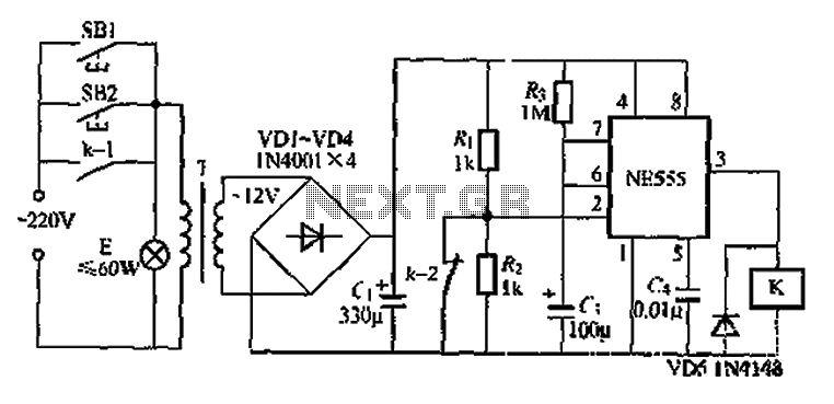
Another application involves the use of a NE555 delay lamp circuit, where components SB1 and SH2 act as J-light buttons that can be installed in two different locations. The lamp can be activated by pressing either SB1 or SB2,...
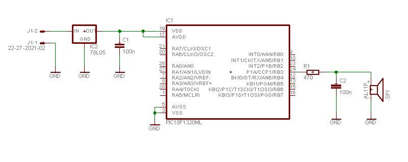
This project enables a PIC microcontroller to play audio PCM sounds using PWM modulation. Pulse-code modulation (PCM) is a digital representation of audio signals. The project utilizes a PIC microcontroller, which is programmed to generate audio signals through pulse-width modulation...

The 555 Astable generates a clock for this circuit, functioning as an oscillator that produces a square wave output at pin 3. This output is counted by the CD4017 decade counter, which creates a running lights effect. The CD4017...
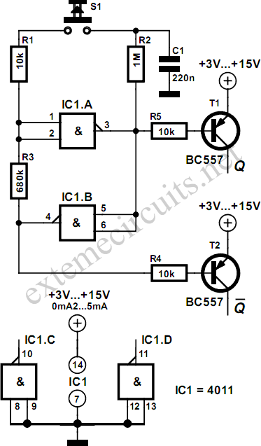
Using just two NAND or inverter gates, it is possible to build a D-type (or toggle) flip-flop with a push-button input. At power-up, the output of gate N2 is at a logical 1, ensuring that transistor T2 is switched...
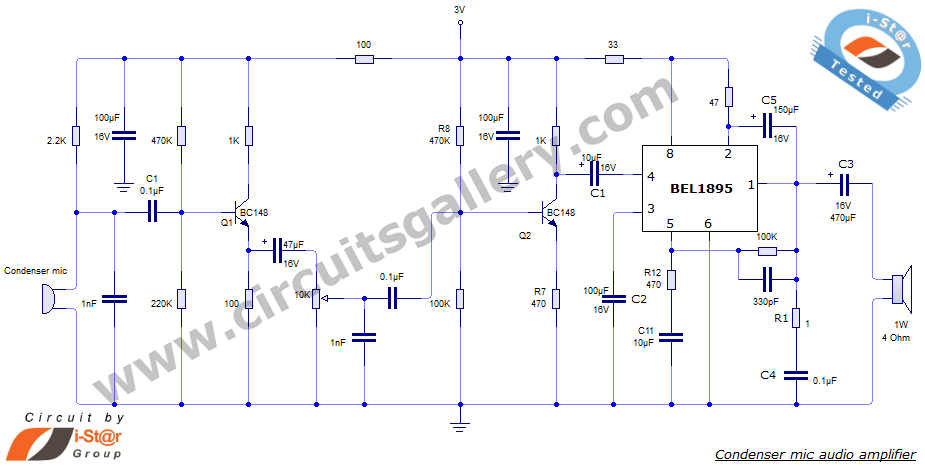
This document presents an audio amplifier circuit suitable for use in walkie-talkies, low-power transmitters, and packet radio receivers. The circuit utilizes a condenser microphone audio amplifier that delivers high-quality audio output of 0.5 watts at 3 volts. The design...