
pic sound player pcm to pwm converter using pic18f1320
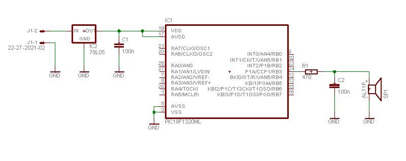
The project utilizes a PIC microcontroller, which is programmed to generate audio signals through pulse-width modulation (PWM). In this setup, the microcontroller converts digital audio data into an analog signal that can be output to a speaker or other audio transducer. The PWM technique allows for the simulation of varying audio amplitudes by rapidly switching the output voltage between high and low states, effectively creating a series of pulses that represent the audio waveform.
The core of the design involves configuring the microcontroller's timer to generate PWM signals at a specific frequency, which corresponds to the desired audio sample rate. The audio data is typically stored in an array within the microcontroller's memory, and the PWM output is modulated according to the values in this array. As the microcontroller iterates through the audio data, it adjusts the duty cycle of the PWM signal, thereby varying the output voltage and producing sound.
For optimal performance, it is important to filter the PWM output to smooth out the digital signal into a more continuous analog waveform. This can be accomplished using a low-pass filter, which eliminates high-frequency components and allows the desired audio frequencies to pass through. The resulting audio output can then be amplified using an audio amplifier circuit to drive speakers or headphones.
Overall, this project demonstrates the effective use of PWM modulation for audio playback in embedded systems, showcasing the capabilities of PIC microcontrollers in generating high-quality sound from digital audio data.This project makes a PIC microcontroller play audio PCM sounds using PWM modulation! Pulse-code modulation (PCM) is a digital representation of.. 🔗 External reference
Related Circuits
The Z86E02 is one of ZiLOG's most popular Z8 One Time Programmables (OTPs). It features a 512-byte EPROM, 61 bytes of RAM, 14 I/O ports, a Watch-Dog Timer, Power-On Reset, a Low-Voltage Protection circuit, and an additional Timer. Notable...
This is a JENS MADSEN project I've built to program my PIC and EEPROM (16xXXX AND 12CXXX AND 24CXX). I use it with IC-Prog; it is little, simple to build, cheap, and gives few bugs. More: When I built...
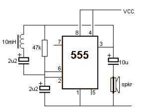
A very simple metal detector electronic project can be designed using a simple 555 timer integrated circuit. As you can see in the schematic circuit, this electronic project requires few external electronic parts. This circuit detects metal and also...
As the demand for VRM output current increases, the components and parts of the SR-Buck converter can no longer meet the requirements for the new generation microprocessors needing 100 A. Additionally, creating filtering inductance for high currents is quite...
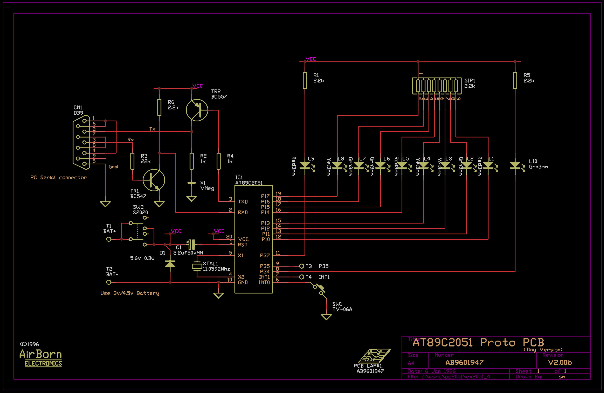
The example program included with the PG2051 evaluation kit is a basic serial to parallel converter written in 8051 assembler. This is probably a good example of the uses to which an AT89C2051 can be put - it would...
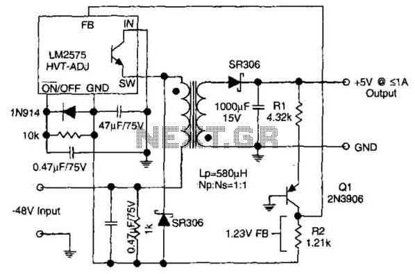
The circuit supplies 1 A at +5 V from the -48 V supply commonly used in telephone equipment. More: The National Semiconductor LM2575 is a simple switching regulator. The circuit utilizes the National Semiconductor LM2575, which is a step-down (buck)...
Warning: include(partials/cookie-banner.php): Failed to open stream: Permission denied in /var/www/html/nextgr/view-circuit.php on line 713
Warning: include(): Failed opening 'partials/cookie-banner.php' for inclusion (include_path='.:/usr/share/php') in /var/www/html/nextgr/view-circuit.php on line 713