
LED flashing with 3909 IC circuit

The project employs the 3909 integrated circuit (IC), which is a versatile component commonly used in various electronic applications, particularly in timer and oscillator configurations. The 3909 IC operates efficiently at a low voltage of 1.5 volts DC, making it suitable for battery-powered circuits.
In a typical application, the 3909 can be configured to function as a timer, allowing for precise control of timing intervals. This IC features multiple pins, including those for power supply, ground, and various output configurations. The circuit may include passive components such as resistors and capacitors, which are essential for setting the timing characteristics of the IC.
For instance, the timing interval can be adjusted by changing the values of the resistors and capacitors connected to the timing pins of the 3909. A larger capacitor will generally increase the timing period, while a smaller one will decrease it. Resistors in series or parallel with these capacitors will also affect the charge and discharge cycles, thus influencing the overall timing behavior of the circuit.
The power supply of 1.5 volts DC can be derived from standard batteries, such as AA or AAA cells, ensuring portability and ease of use. The circuit design should include appropriate bypass capacitors near the power supply pins of the IC to filter out noise and provide stability during operation.
Overall, this project with the 3909 IC offers a straightforward yet effective way to implement timing functions in various electronic applications, with a focus on low-power consumption and simplicity.This project uses a 3909 IC and a few other parts; power is 1.5 volts DC. 🔗 External reference
Related Circuits

2 versions of the equalization circuit, the first having 6 dB less insertion loss than the other. However, some may not be able to find a 0.68 microfarad capacitor. The second version uses a more common 0.22 microfarad capacitor....
This page features a circuit that has twenty open collector outputs that turn on one at a time in a continuous sequential manner. The circuit utilizes the 74LSxx family of TTL integrated logic devices. The circuits are designed to...

The circuit utilizes a 555 Integrated Circuit (IC) configured as a delay circuit. It transitions from a low to a high state after a button (SB) is pressed, initiating a delay before the output terminal goes high. The output...
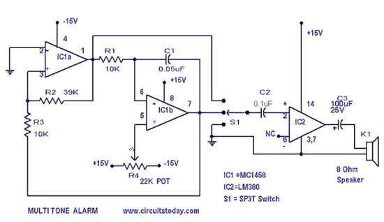
A simple alarm circuit with a diagram and schematic that generates a multi-tone sound. This alarm circuit is suitable for use in burglar alarms and sirens and is designed using dual op-amps MC1458 and LM380. The described alarm circuit utilizes...
This circuit gradually illuminates a 120VAC lamp over an approximate 20-minute period. A bridge rectifier converts the AC voltage to 120V DC, supplying power to the MOSFET and the 60-watt lamp. A 6.2K, 5-watt resistor along with a Zener...
Here is the schematic diagram for a 20 Watt driver. I developed this circuit in 1985, and used it to build a lamp that found much use both as camping light and as emergency light during the then-frequent power...