
555 IC using a delay circuit ter
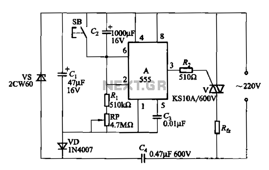
The 555 timer IC is a versatile component widely used in timing applications. In this configuration, the 555 timer operates in monostable mode, where it generates a single output pulse in response to a trigger input. When the button SB is pressed, it triggers the timer, initiating the timing cycle. The timing duration is determined by the resistor (R) and a capacitor (C) connected to the 555 timer, following the formula:
\[ T = 1.1 \times R \times C \]
Where T is the time delay before the output transitions to a high state. The potentiometer (R) allows for fine-tuning of the resistance, thus adjusting the time delay according to the application's requirements.
Upon the completion of the delay period, the output pin (usually pin 3 of the 555 IC) goes high, providing a voltage signal that can be used to drive a load. This load can be a relay or contactor, which are electromechanical devices that can switch larger currents and voltages than the 555 timer can handle directly. By connecting the relay or contactor to the output pin, the circuit can effectively control high-power devices, such as motors or lighting systems, allowing for versatile applications in automation and control systems.
To ensure proper operation, it is essential to select the appropriate values for the resistor and capacitor to achieve the desired delay time. Additionally, the relay or contactor must be rated for the load it is intended to control, ensuring safe and reliable operation. The circuit can be powered using a DC supply suitable for the 555 timer, typically between 4.5V and 15V, depending on the specific requirements of the application.
Overall, this 555 timer-based delay circuit provides a simple yet effective solution for applications requiring a timed output signal, with the flexibility to control larger loads through the use of relays or contactors.555 IC using a delay circuit ter It is the transition from low to high delay circuit. Ie after pressing the button SB, after a delay after birth, the output terminal goes high and remain so until the shut down. Adjusting potentiometer R, you can change the delay time. Rfz load can be changed to relay or contactor, etc., and then by their contacts to control larger loads.
Related Circuits
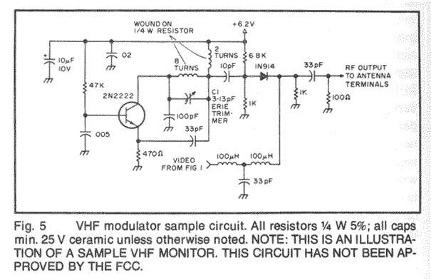
The project involves designing and constructing a wireless transmitter that operates on FM frequencies, enabling the transmission of video and audio signals over a specified distance to an FM tuner. This development addresses the growing demand for portability and...
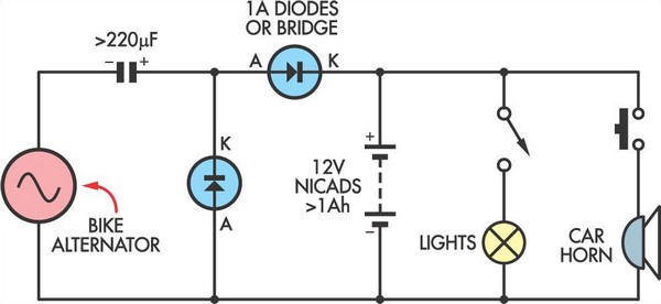
This simple circuit enables a 12V battery pack to be charged using a bike generator. The generator is rated at 3W and, with the inclusion of a voltage multiplier circuit, delivers approximately 200mA at a speed of around 15...
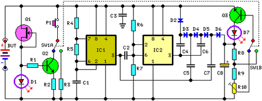
FET Q1 functions as a constant current generator, providing biasing for LED D1 and the base of Q2. This configuration ensures that D1 emits light at a consistent intensity, regardless of the battery voltage, which ranges from 3 to...
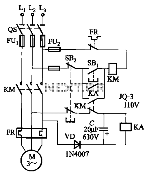
The circuit illustrated in Figure 3-73 is designed to utilize the power generated by instantaneous power failures, specifically the self-induced electromotive force (emf) produced by the motor, to implement an immediate shutdown protection mechanism. During a momentary power outage,...
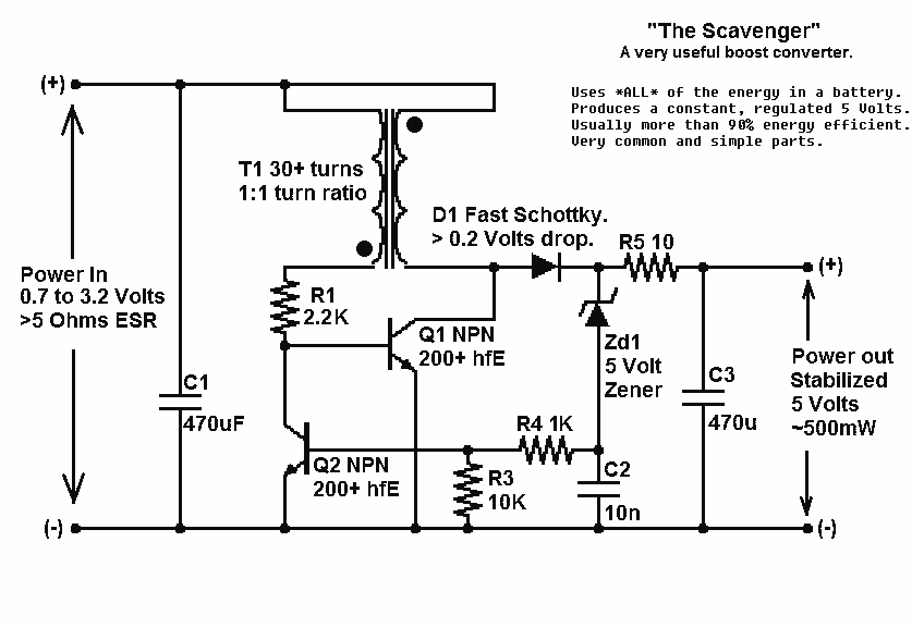
Presented here is a significant advancement in the design of simple, cost-effective, and efficient boost converters. To achieve an effective design, it is essential to convert current to voltage as efficiently as possible. This circuit excels in this regard. The...
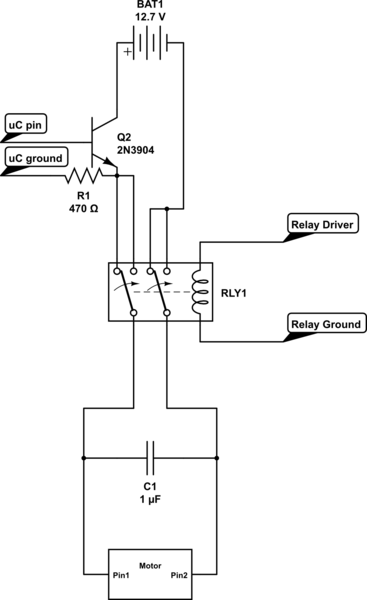
Control the state (on/off) and direction of two linear actuators that are essentially DC motors. The linear actuators operate at 12VDC and draw 10 amps of current at full load. A 25A external power supply has been purchased, as...
Warning: include(partials/cookie-banner.php): Failed to open stream: Permission denied in /var/www/html/nextgr/view-circuit.php on line 713
Warning: include(): Failed opening 'partials/cookie-banner.php' for inclusion (include_path='.:/usr/share/php') in /var/www/html/nextgr/view-circuit.php on line 713