
12 Volt Fluorescent Lamp circuits
The circuit schematic for the 20 Watt driver is designed to operate a fluorescent tube efficiently, utilizing a push-pull oscillator configuration formed by two transistors. These transistors are biased to prevent crossover conduction, which is critical for maintaining efficiency and stability during operation. The inclusion of a 1.5 Ohm resistor ensures that the bases of the transistors are self-biased to a slightly negative voltage, thus preventing unwanted conduction during idle periods.
A significant feature of this design is the use of a 220 µF capacitor, which provides a strong positive bias during startup, enabling the oscillator to initiate and stabilize quickly. The 2.2 kOhm resistor serves a crucial role in discharging the capacitor when the circuit is powered down, allowing for reliable restarts on subsequent power applications.
The core of the circuit employs a ferrite core salvaged from a flyback transformer, with the primary and feedback windings configured on one leg, while the secondary windings that connect to the fluorescent tube are placed on the opposite leg. This arrangement is vital for achieving effective magnetic coupling, which is the primary source of ballasting in this configuration.
An "ionization antenna" made from a simple wire runs along the length of the fluorescent tube, facilitating gas ionization upon power-up. This feature enhances the efficiency of the lamp, as the initial discharge is sufficient to heat the tube filaments, leading to a rapid increase in discharge and full lamp operation within seconds of power application.
The circuit is designed with a minimal component count of eight, which contributes to its compactness and simplicity. It employs a CMOS hex inverter as an oscillator, driving a MOSFET that controls a high-voltage autotransformer. The transformer, in conjunction with a ballast capacitor, ensures that the fluorescent tube operates with true alternating current, enhancing efficiency.
In contrast to other designs, such as the 8 Watt driver, this circuit incorporates a choke in the DC supply, which mitigates mutual conduction issues between the transistors. This modification results in cleaner DC input and significantly reduces the need for extensive filtering. The output waveform achieves a near sine wave shape, minimizing radiated noise, making it suitable for use in sensitive environments, such as radio stations.
The design utilizes high-gain transistors, which can be replaced with lower gain alternatives if adjustments are made to the bias resistor value. Notably, the circuit operates without the need for heat sinks, making it even more practical for various applications.Here is the schematic diagram for a 20 Watt driver. I developed this circuit in 1985, and used it to build a lamp that found much use both as camping light and as emergency light during the then-frequent power outages. The two transistors work as a push-pull oscillator. To avoid crossover conduction, during operation the bases are self-biased to a slightly negative voltage by the 1R5 resistor.
The 220uF capacitor gives strong positive bias during power-up, in order to get the oscillator started. 2k2 resistor's only purpose is discharging the capacitor when the circuit is switched off, so it will restart the next time too!
I used a ferrite core salvaged from an old 12" black and white TV flyback transformer. I wound the primary and feedback windings on one leg of the core, and the windings going to the tube on the opposite leg. This arrangement is crucial for the circuit to work! The only ballasting action in this circuit is the imperfect magnetic coupling between the primary and secondary coils!
You may be wondering about the "ionization antenna" in the schematic. This is simply a piece of wire that runs along the entire length of the tube. You can stick it there with tape, or you can string it from socket to socket, like I did. Striving for the highest possible efficiency, I came up with the design shown in this schematic diagram. A CMOS hex inverter is used as an oscillator and driver for a MOSFET, which drives a high voltage autotransformer that feeds the fluorescent tube via a ballast capacitor.
The circuit is very simple and small, uses just 8 components, yet it is extremely efficient (I could not measure the loss, it seems to be below 3%), and it drives the tube with true AC, despite the simplicity! The tube filaments are not explicitly heated. On powerup, the gas ionizes from the high voltage alone, and the small discharge that starts has enough anodic heating effect to warm up the filaments.
Soon the discharge increases, generates a runaway effect, and less than a second after applying power the tube is fully on, working at the 30 V level, with the ballast capacitor limiting the current. The schematic for the 8 Watt driver will show you that this design is quite different from both previous ones.
It uses capacitive ballasting like the 2 Watt driver, and a two-transistor saturation-limited oscillator like the 20 Watt design. But note an important difference: This circuit has a choke added in the DC supply, that produces more effects than you may think: Thanks to this choke, mutual conduction between the two transistors is no longer a problem, allowing for a very simple drive scheme and almost lossless operation.
The input current becomes almost clean DC, minimizing further filtering requirements. And the waveform becomes a quite clean sine wave, which gives a tremendous advantage in terms of radiated noise! This lamp can be used in a radio station without causing any interference. The transistors used in this design are high-gain types. I just happened to have them on hand, salvaged from an old video recorder. You can use lower gain transistors, but then you must lower the value of the bias resistor (2k7 in my design).
No heat sinks are required. 🔗 External reference
Related Circuits
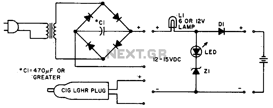
Lamp LI will glow brightly while the LED remains off when the battery is low and charging. Conversely, the LED will illuminate brightly, and the light bulb will be dim when the battery is nearly charged. Lamp LI should...

The BC547 transistor has a maximum operating current of 100 mA and a maximum voltage rating of 65 volts. When oriented with the label facing the viewer, the three terminals from left to right are collector, base, and emitter....
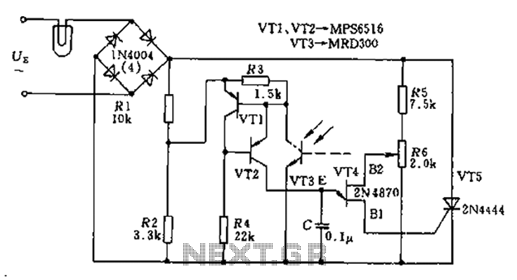
The circuit utilizes a thyristor-based AC automatic voltage regulator to stabilize the brightness of lamp L. A diagonal line connects the thyristor to the T5 bridge. The trigger pulse for the thyristor is generated by a single-junction transistor, VT4....
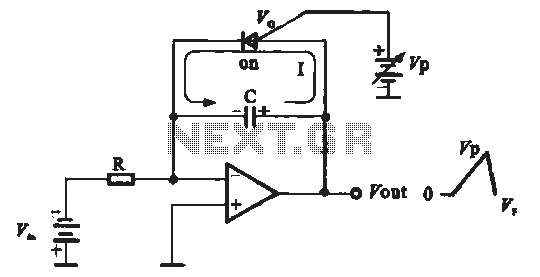
A sawtooth voltage-controlled oscillator operates by first generating a negative potential maximum at the output of the comparator. This output is then fed to the inverting input terminal through resistor R1, which is part of the relaxation oscillator. The...
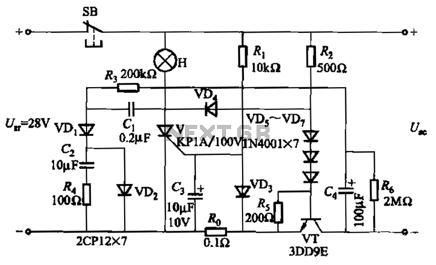
Capacitor C3 is used to determine the cutoff power, specifically the voltage threshold (VT cutoff), which influences the delay time selection. The schematic includes a reset button, SB, that is utilized to reset the system after a failure has...
This simple circuit is a good solution to the powering a dual supply op amp from a single battery problem. The circuit simply takes a positive voltage and inverts it. It uses only one 555 timer and a few...