
led How can I effectively reduce the voltage needed to activate a transistor

To address the issue of insufficient voltage from the audio line output of smaller devices, an operational amplifier can be integrated into the circuit design. The op-amp will serve to amplify the audio signal before it is fed into the TIP31C transistor, ensuring that the necessary voltage levels are achieved for proper operation of the LED strip.
For this application, a suitable op-amp could be the LM358, which is a dual op-amp that can operate from a single power supply, making it ideal for battery-powered devices. The op-amp can be configured in a non-inverting amplifier mode to increase the voltage level of the audio signal. The gain can be set using two resistors (R1 and R2) where the gain (A) is defined as A = 1 + (R2/R1). Selecting appropriate resistor values will allow for the desired amplification to ensure the output signal exceeds the activation threshold of the TIP31C transistor.
The circuit configuration would involve connecting the audio line output to the non-inverting input of the op-amp. The output of the op-amp will then be connected to the base of the TIP31C transistor. A resistor should be placed between the base of the transistor and the output of the op-amp to limit the base current. Additionally, a pull-down resistor can be connected from the base to ground to ensure the transistor remains off when no signal is present.
The emitter of the TIP31C should be connected to ground, while the collector connects to the LED strip. A suitable current-limiting resistor must be placed in series with the LED strip to prevent excessive current from damaging the LEDs. The power supply for the circuit should be chosen based on the voltage and current requirements of the LED strip, ensuring it can provide sufficient power for all 200 LEDs to light up effectively.
This configuration should resolve the insufficient voltage issue when using smaller music-playing devices, allowing the LED strip to flash in time with the music as intended. Proper testing and adjustment of resistor values may be necessary to achieve optimal performance.A circuit which basically connects the line out (audio output) of a music playing device to a set of LEDs (actually a huge strip of around 200 LEDs), so they flash in time with the music (from internet tutorials - I`m a bit of beginner). My circuit works very well using my laptop as the audio device (connecting my circuit to the headphone jack on it).
But when I use something smaller such as an iPod, the lights barely turn on at all. I`ve tried using a Darlington Pair (below), but that makes the issue worse. This is why I think the issue is that the audio line out is not reaching the 0. 7 volts across the base and emitter that the TIP31C transistor needs to activate (the Darlington Pair means it now needs 1. 4 volts to activate). From my research, it looks like using an op amp might be the way forward, to amplify the audio line out signal before the TIP31C transistor.
Would somebody be able to suggest one, and which inputs I should connect to 🔗 External reference
Related Circuits
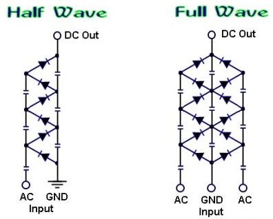
How to create a voltage multiplier using diodes and capacitors, capable of producing extremely high voltage. A voltage multiplier is a circuit that converts a lower AC or DC voltage into a higher DC voltage using a combination of capacitors...
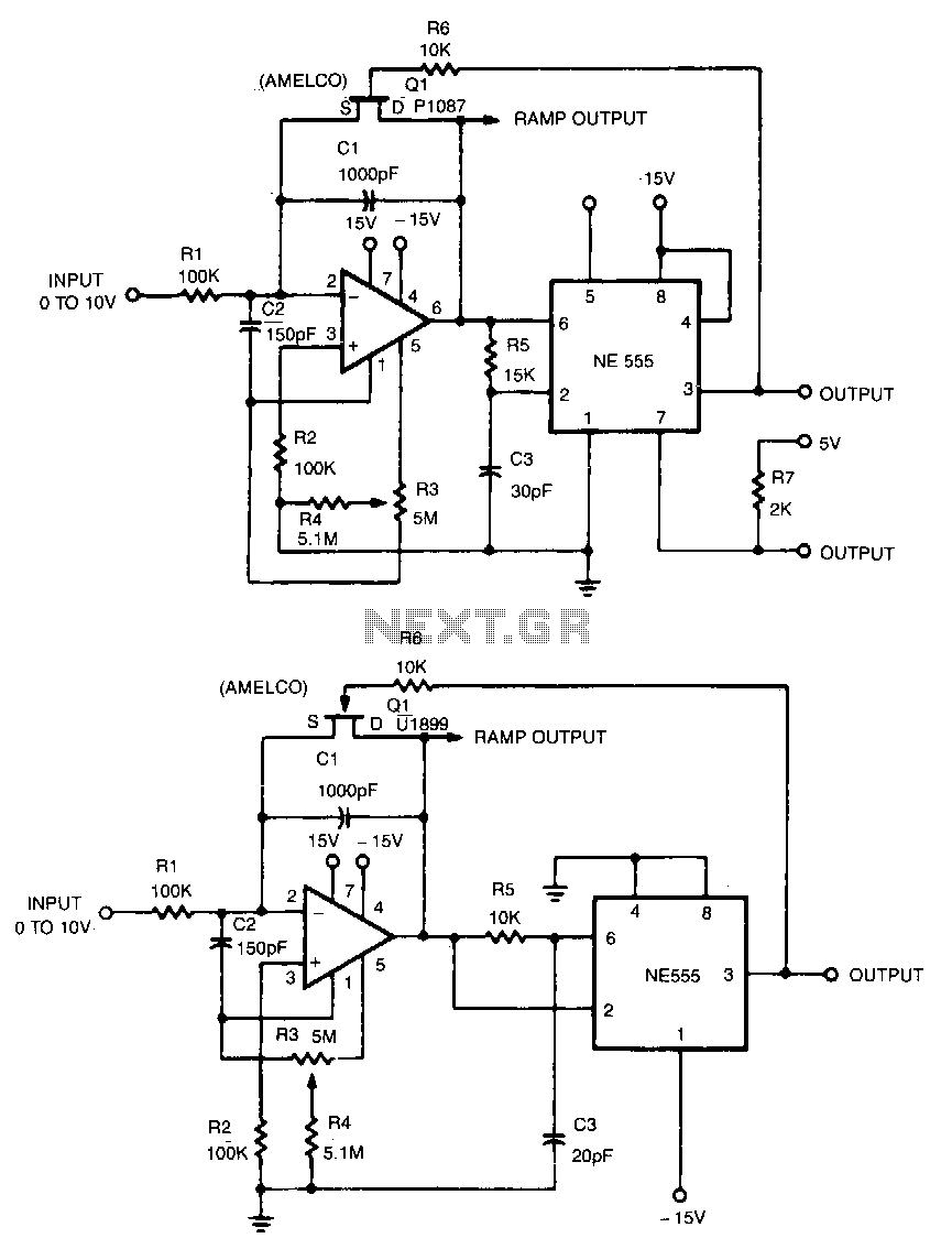
This linear voltage-to-frequency converter achieves good linearity over the range of 0 to -10 V. Its mirror image provides the same linearity over the range of 0 to +10 V; however, it is not compatible with DTL or TTL. The...

The product requires a voltage-controlled, current-limited power supply. Various switcher chips have been used with an op-amp to provide feedback for a current sense voltage to the feedback pin. Currently, an LM22680 is in use, but it has shown...
This design is for an interpolating scanner, a circuit featuring multiple signal inputs, a control voltage input, and a signal output. The output selectively transitions between inputs, smoothly fading from one to the next as the control voltage increases....
The LM3915 is a monolithic integrated circuit that senses analog voltage levels and drives ten LEDs providing a logarithmic 3 dB/step analog display. LED current drive is regulated and programmable, eliminating the need for current limiting resistors. More: This...
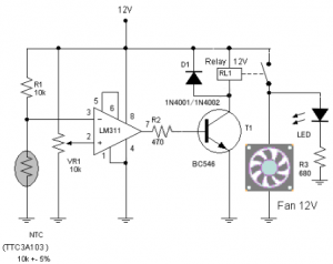
The circuit schematic diagram of a fan speed control system that activates only when necessary. When the transistor heats up, the fan will automatically turn on. The fan speed control circuit operates based on the temperature of the transistor, utilizing...