
LED Indicator Light Circuit diagram

The circuit employs a 555 timer configured in astable mode to generate a pulse-width modulation signal, which controls the LED indicator's blinking pattern. The frequency of the blinking can be adjusted by varying the resistors and capacitors connected to the timer. This flexibility allows for customization of the blinking rate to suit specific requirements for visibility and signaling.
The BCD 7490, a binary-coded decimal counter, is integrated into the design to manage the timing and sequencing of the LED indicators. It counts the pulses generated by the 555 timer and can drive multiple LEDs in a sequence, enhancing the visual indication for direction signaling. The outputs of the BCD 7490 can be connected to various LEDs, ensuring that the indicators operate in a clear and recognizable manner.
Resistors in the circuit are crucial for limiting current to the LEDs, preventing damage and ensuring longevity. The selection of these resistors is based on the forward voltage and current ratings of the LEDs used. Additionally, the circuit may include capacitors for smoothing the power supply and reducing noise, which can improve the performance and reliability of the indicator system.
Overall, this project demonstrates a practical application of basic electronic components, showcasing how a combination of timers, counters, and resistors can create an effective signaling mechanism for vehicles.LED indicator in this project can be use in the bike indicator or car direction indicator. Time 555 and BCD 7490 are use with few resistors more than 100+ electronics projects. 🔗 External reference
Related Circuits
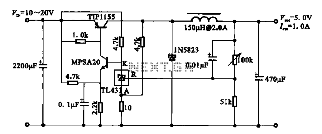
The 5V regulator circuit is designed to convert a DC input voltage ranging from 10V to 20V into a stable 5V output. This circuit features low power consumption and high efficiency. The 5V regulator circuit typically employs a linear voltage...
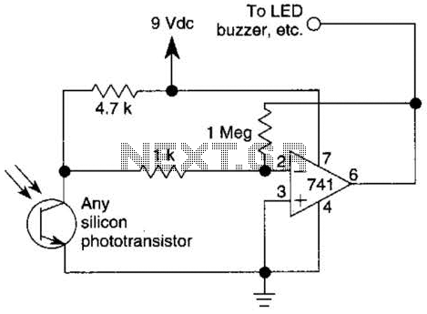
This circuit represents one of the simplest infrared (IR) receivers that can be constructed. The components are inexpensive, the layout is not critical, and a 9-V battery provides a long operational life. The described IR receiver circuit typically consists of...
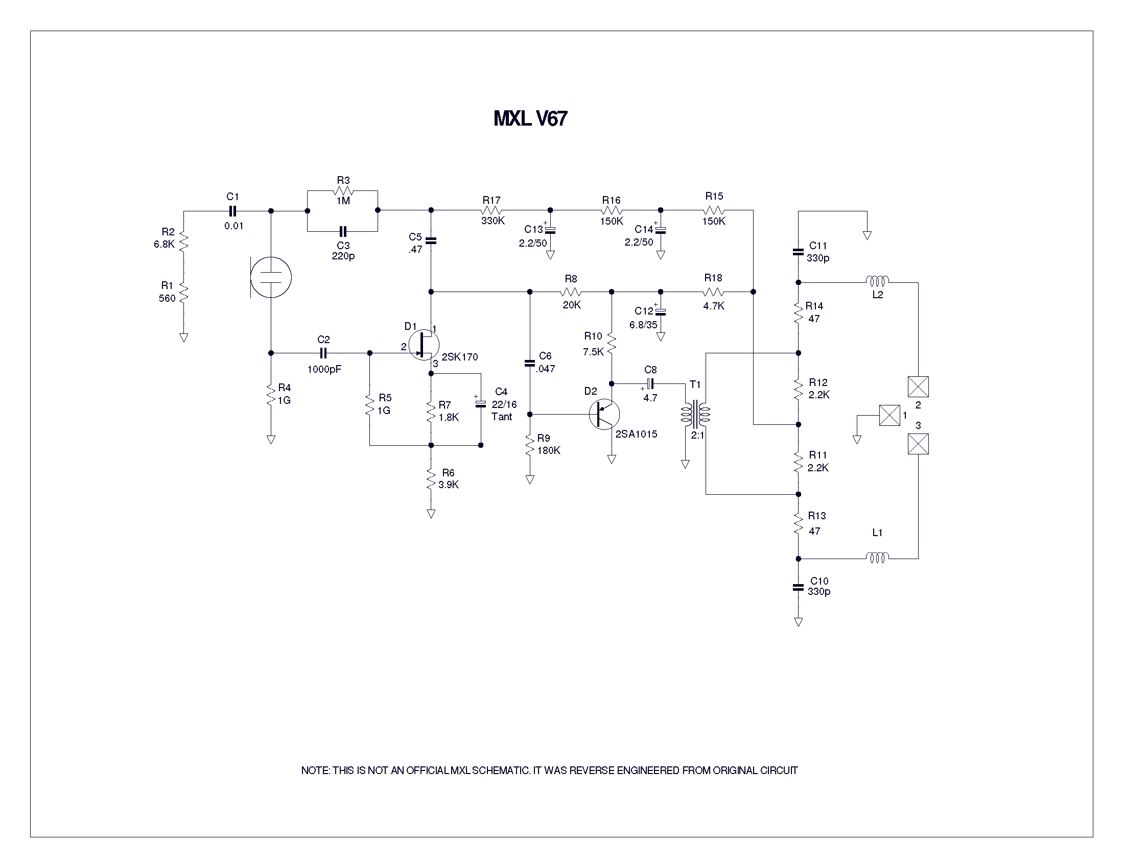
A user has been experimenting with modifications to a budget-friendly MXL V67s microphone to enhance its performance, specifically aiming to improve the condenser quality until a higher-end model can be acquired. The MXL V67s is a popular choice among budget-conscious...
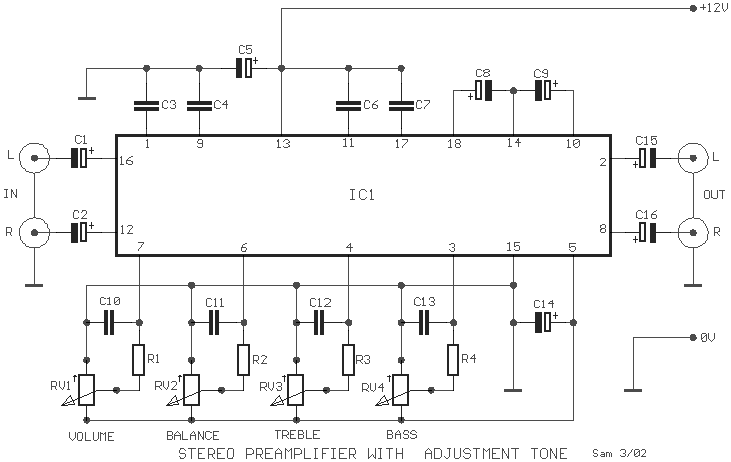
A simple preamplifier circuit is often required, utilizing a few components for ease of construction. This circuit employs an operational amplifier, specifically the Motorola TCA5550, which features a dual amplifier configuration. It provides outputs for adjusting volume, balance, treble,...
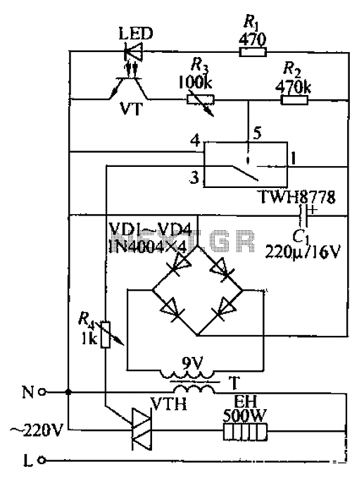
Bathroom automatic hand dryer circuit. The circuit features an LED and a photosensitive transistor (VT) that together form an infrared opto coupler, serving as a signal sensing mechanism. The control element is a 1WH8778 switch integrated circuit. When hands...
Since then, NL has evolved into the Microsoft Windows®-based NL4, which has been extensively used by world-class engineers in various fields of electronics for almost 10 years. NL5 is the first version to be publicly available. Unlike conventional SPICE-based...